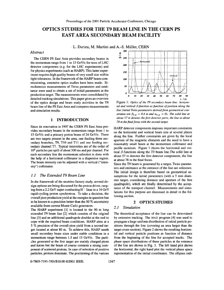
Proceedings of the 2001 Particle Accelerator Conference, Chicago OPTICS STUDIES FOR THE T9 BEAM LINE IN THE CERN PS EAST AREA SECONDARY BEAM FACILITY L. Durieu, M. Martini and A.-S. Muller, CERN e . 300 Abstract 250 The CERN PS East Area provides secondary beams in the momentum range from 1 to 15 GeV/c for tests of LHC detector components (e.g. for the LHC experiments) and for physics experiments (such as HARP). This latter experiment requires high quality beams of very small size within tight tolerances. In the framework of the HARP beam commissioning, extensive optics studies have been made. Simultaneous measurements of Twiss parameters and emittance were used to obtain a set of initial parameters at the production target. The measurements were consolidated by detailed tracking simulations. This paper gives an overview of the optics design and beam study activities in the T9 beam line of the PS East Area and compares measurements and simulation results. 200 150 100 50 0 0 1.1 The Extended T9 Beam Line In the framework of the neutrino factory study, several design options are being discussed for the proton driver, ranging from a 2.2 GeV super-conducting H - linac to a 16 GeV rapid-cycling proton synchrotron. To take a decision, the overall pion production yield at the energies in question has to be known to a precision better than the 50 % uncertainty available from current Monte Carlo generators. The HARP experiment [l] is located in the 90 m long extended T9 beam line [2] which consists of the original line [3] and an additional quadrupole doublet at the end to cope with the required beam conditions. HARP aims at a 5 % precision of the overall pion yield from a second target located at about 80 m. To achieve this, HARP needs small secondary beam sizes under stable conditions in a momentum range between 1.5 and 15 GeV/c. The particles generated at the first target are mainly charged pions and kaons but the beam of course contains a strong component of scattered protons. In case of selection of positive particles, protons dominate. The positioning of the various 0-7803-71 9 1-7/01/$10.00 02001 E E E . 20 30 40 50 60 70 80 90 s /m Figure 1: Optics of the T9 secondary beam line: horizontal and vertical /3-function asfinction of position along the line (initial Twiss parameters derived from geometrical constraints are & = 0.4 m and = 0). The solid line at about 57 m denotes the first detector parts, the line at about 78 m the final focus with the second target. 1 INTRODUCTION Since its renovation in 1997 the CERN PS East Area provides secondary beams in the momentum range from 1 to 15 GeV/c and a primary proton beam of 24 GeV/c. There are two targets present in the area, one feeding three secondary branches, “9, TI0 and T11 and one feeding secondary channel Ti’.Typical intensities are of the order of IO6 particles per spill of about 300 ms and per channel. For each secondary line the momentum selection is done with the help of a horizontal collimator in a dispersive region. The beam intensity can be adjusted with a vertical (“intensity”) collimator. 10 HARP detector components imposes important constraints on the horizontal and vertical beam size at several places along the line. Further constraints are given by the local aperture of the magnetic elements and the need to have a reasonably small beam at the momentum collimator and profile monitors. Figure 1 shows the horizontal and vertical @-functionsalong the T9 beam 1ine.The solid line at about 57 m denotes the first detector components, the line at about 78 m the final focus. Since the T9 beam is generated by a target, Twiss parameters and emittance at the entrance of the line are unknown. The initial design is therefore based on geometrical assumptions for the initial parameters (with a 5 mm diameter target, considering distance and aperture of the first quadrupole), which are finally determined by the acceptance of the transport channel. Measurements and simulations for this purpose are discussed in detail in the following section. 2 OPTICS STUDIES 2.1 Simulation The theoretical acceptance of the line can be determined by extensive tracking. The MAD program [4] was used to propagate a large uniform distribution of initial particle positions through the line (covering an area larger than the target cross-section). Figure 2 shows the resulting horizontal and vertical particle positions as function of distance from the beginning of the line for accepted tracks. The phase space distributions of these particles at the entrance of the line are shown in Fig. 3. The left hand plot shows the horizontal, the right hand plot the vertical phase space representation of the initial coordinates. The ellipses indi- 1547 Proceedings of the 2001 Particle Accelerator Conference, Chicago E E 75 50 ;25 0 -15 -sa -7s -100 0.1 an 0.11 a16 a18 a2 031 034 0.16 h I mJ 0 10 20 30 40 50 60 70 80 Figure 4: Measured RMS beam size as function of normalised quadrupole gradient k. The filled circles with er- 90 slm ror bars represent the measured beam sizes, the curve corresponds to thefit. Figure 2: Results of M A D [ 4 ] tracking for the Z 9 beam line. The upper plot shows the horizontal, the lower one the vertical particle position asfunction of distance from the beginning of the line. measured beam sizes. Therefore these scans can be used to extract the beam matrix elements by a fit, and extrapolation to the entrance of the line. Figure 4 shows such a scan. The filled circles with error bars represent the measured beam sizes, the curve corresponds to the fit. The beam emittances extracted from these scans are c5 = (10.5 f 1.1) pm and = (3.9 f 1.4)pm. The corresponding Rviss parameters were measured to be a, = -(0.4 f 0.6), a y = 2.2 f 4.3, Px = (0.85 0.4) m and &, = (0.9f 1.1) m. Additional systematic uncertainties arise from the non-Gaussian shape of the beam which is caused by collimation. This might prevent the beam filling the phase space ellipse completely and therefore alter the determination of the ' h i s s parameters. cate the reconstructed initial Twiss parameters and acceptances obtained from the calculation of the equivalent RMS emittance according to E R M S = J(u2)(ut2, - ( U U ' ) ~ with a = - ( U U ' ) / & R M S and p = ( u 2 ) / & ~ where ~s, U stands for the horizontal or vertical plane and providing that (U)and (U') vanish. Statistical uncertainties are given, derived from higher order moments of the distribution. The acceptances obtained by tracking are a, = (12.7 f 0.3) pm and ay = (15.1 f 0.3) pm. The initial parameters derived from the theoretical acceptance are a, =0.22&0.03,a, =0.6250.04,Px =(1.7950.05)m 3 OPERATIONAL ASPECTS and PY = (1.87f 0.05)m. These p-functions are obviously The operation of the HARP experiment requires comparalarger than those calculated from geometrical constraints ble beam conditions over the full momentum range. This is (see Fig. 1) but show the same aspect ratio. made difficult by the increase in multiple Coulomb scatter2.2 Measurement ing at lower momenta. Several detectors are placed in the Simultaneousmeasurementsof Tbiss parameters and emitbeam line (for example time-of-flight scintillators) and the tance were performed with "scans" of quadrupole gradi- beam has to pass through air. This leads to an emittance ents. In this method, the beam size is measured with blow-up caused by multiple scattering. This emittance inprofile monitors (multi wire proportional chambers, MWcrease is given by [ 5 ] PCs, in the case of T9) as function of the quadrupole gradient. The beam size at a given point is described by aZll= C:ctl +2SiCici2+S:ciz, where Ci and Si are elements of the transformation matrix from the point of meawhere ao, Po and 70 are the Twiss parameters at the scatsurement to the point of interest, the c ! ~are elements of the terer, L the thickness of the obstacle and the RMS beam matrix at the point of interest and the oi,ll are the - 4.- 30 Figure 3: Horizontal (lejrand vertical (right)phase'; r e 40 SO 60 70 80 90 slm Figure 5: Estimated accumulated (normalised) emittance blow-up (A&)as function of position in the beam line. Hor- representation of accepted tracks (759 from 24000 generated). From these distributions, Twiss parameters at the target at the entrance of the line can be approximated, which are indicated by the ellipses. izontal and vertical emittance blow-up are shown for a momentum of I5 GeVk. 1548 Proceedings of the 2001 Particle Accelerator Conference, Chicago m 0 20 40 Man U35 s,gm IJ69 60 80 0 20 40 60 80 Vertical I nun HorizontalI mm Vertical I mm Horizontal I mm 0 2 4 6 8 IO I2 I4 I6 p I GeVlc Figure 7: Measured beam size as function of momentum. 0 10 40 60 80 0 Verucal I mm E, 10 40 60 The upper plot shows the horizontal, the lower plot the vertical RMS beam size. Thefilled symbols correspond to measurements done in 2000, the open symbols to measurements of 2001. The increase in beam size for lower momentum due to multiple Coulomb scattering is clearly visible. 80 Honzontal I nun Horizontal = 10.06 = 1.95 Figure 6: Beam profiles measured with the three HARP beam chambers kindly provided by P: Gorbounov of the HARP collaboration. The lefl hand column shows vertical, the right hand column horizontal beam profiles. The threefold measurement allows an on-line estimation of the emittance (quoted below the plots) which is in reasonable agreement with the quadrupole scan measurements. scattering angle [6] = 13.6 z PP xo (1 + 0.038 In this equation, XOis the radiation length, z, p and p are the charge state, total momentum (in MeV/c) and velocity of the incident ion relative to the speed of light. Figure 5 shows the estimated accumulated (normalised) emittance blow-up (Ae) as function of position in the beam line. Horizontal and vertical emittance blow-up are shown for a momentum of 15 GeV/c. The significant increase in horizontal emittance due to scattering in a high-@region is clearly visible. As a consequence, the amount of material in the beam path was reduced and the most disturbing scatters moved to a place of lower p. As a result, the beam size contribution from scattering was reduced by about a factor two. To survey beam quality and steering, the HARP experiment is equiped with its own MWPCs. Figure 6 shows beam profiles measured with these chambers. The left hand column shows vertical, the right hand column horizontal beam profiles. This threefold measurement allows an on-line estimation of the emittance using the known transfer matrix. The quoted result is in reasonable agreement with the results obtained by quadrupole scans. Figure 7 finally shows the beam size as function of momentum measured in 2000 and in 2001. The upper plot shows the horizontal, the lower plot the vertical RMS beam size. The success of repeated beam tuning sessions and the relocation of detectors causing emittance increase by multiple Coulomb scattering is clearly visible. 4 SUMMARY The original T9 beam line has been extended by adding one quadrupole doublet to meet the.tight beam size requirement of the HARP experiment, especially at low momenta where the beam suffers the harmful effect of multiple scattering. Additional constraints such as apertures and the limited strength of existing quadrupoles need also to be considered. The design of the new T9 optics has been verified by extensive tracking using Monte Carlo techniques to derive the acceptance of the channel. Monte Carlo simulations and classical optics design, based on matching with geometrical assumptions for initial parameters, yield both symmetric beta-functions at the entry of T9 line. Experimental results obtained during the commissioning phase of the beam line, after fine tuning and better positioning of some equipment along the line, showed that the beam sizes at all the requested momenta remain within the tolerances of the HARP experiment. 5 ACKNOWLEDGEMENTS Sincere thanks to all who have contributed to the results presented here and especially to J.-Y. HCmery, J.-P. Riunaud and L. Zani for interesting and instructive discussions. 6 REFERENCES [l] M. Catanesi et al. Proposal to study hadron production for the neutrino factory and for the atmospheric neutrino flux. CERN-SPSC 99-35, CERN, November 1999. [2] L. Durieu, M. Giovannozzi, M. Martini, L. Zani. Design of an Extension of the T9 Beam Line for Hadron Production Study. PSICA 99-027, CERN, 1999. [3] L. Durieu, 0. Fernando. Design of T9 (AtlasICMS) for EHNL. PSIPA 96-39, CERN, 1996. [4] H.Grote and E C. Iselin. The MAD Program, User's Reference Manual. SL Note 90-13 (AP) (Rev. 4), CERN, March 1995. [5] A. Muller. Description of Beam-Matter Interaction in the Covariance Matrix Formalism - Application to Modification of Emittance and Twiss Parameter. CERNPS 2001-013 (AE), CERN, May 2001. [6] D.E. Groom et al. Review of Particle Physics. In EM Phys. J. C 15.2000. 1549


