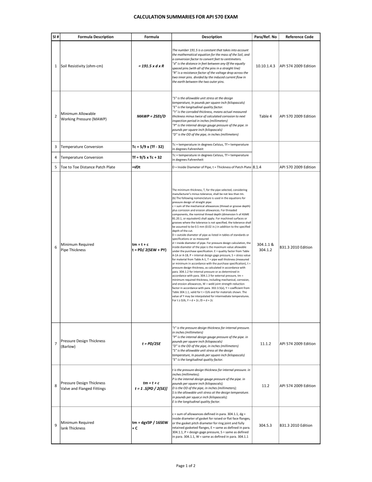
CALCULATION SUMMARIES FOR API 570 EXAM Sl # Formula Description 1 Soil Resistivity (ohm-cm) 2 Minimum Allowable Working Pressure (MAWP) Formula Description = 191.5 x d x R 10.10.1.4.3 API 574 2009 Edition MAWP = 2SEt/D "S" is the allowable unit stress at the design temperature, In pounds per square inch (kilopascals) "E" is the longitudinal quality factor. '"t" is the corroded thickness, means actual measured thickness minus twice of calculated corrosion to next inspection period in inches (millimeters) "P" is the internal design gauge pressure of the pipe. in pounds per square inch (kilopascals) "D" is the OD of the pipe, in inches (millimeters) Table 4 API 570 2009 Edition Tc = 5/9 x (Tf - 32) Tc = temperature in degrees Celsius, Tf = temperature in degrees Fahrenheit 4 Temperature Conversion Tf = 9/5 x Tc + 32 Tc = temperature in degrees Celsius, Tf = temperature in degrees Fahrenheit 5 Toe to Toe Distance Patch Plate =√Dt D = Inside Diameter of Pipe, t = Thickness of Patch Plate 7 8 9 Minimum Required Pipe Thickness Pressure Design Thickness (Barlow) Pressure Design Thickness Valve and Flanged Fittings Minimum Required lank Thickness Reference Code The number 191.5 is a constant that takes into account the mathematical equation for the mass of the Soil, and a conversion factor to convert feet to centimeters. "d" is the distance in feet between any 0f the equally spaced pins (with all of the pins in a straight line) "R" is a resistance factor of the voltage drop across the two inner pins. divided by the induced current flow in the earth between the two outer pins. 3 Temperature Conversion 6 Para/Ref. No tm = t + c t = PD/ 2(SEW + PY) The minimum thickness, T, for the pipe selected, considering manufacturer’s minus tolerance, shall be not less than tm. (b) The following nomenclature is used in the equations for pressure design of straight pipe: c = sum of the mechanical allowances (thread or groove depth) plus corrosion and erosion allowances. For threaded components, the nominal thread depth (dimension h of ASME B1.20.1, or equivalent) shall apply. For machined surfaces or grooves where the tolerance is not specified, the tolerance shall be assumed to be 0.5 mm (0.02 in.) in addition to the specified depth of the cut. D = outside diameter of pipe as listed in tables of standards or specifications or as measured d = inside diameter of pipe. For pressure design calculation, the inside diameter of the pipe is the maximum value allowable under the purchase specification. E = quality factor from Table A-1A or A-1B, P = internal design gage pressure, S = stress value for material from Table A-1, T = pipe wall thickness (measured or minimum in accordance with the purchase specification), t = pressure design thickness, as calculated in accordance with para. 304.1.2 for internal pressure or as determined in accordance with para. 304.1.3 for external pressure, tm = minimum required thickness, including mechanical, corrosion, and erosion allowances, W = weld joint strength reduction factor in accordance with para. 302.3.5(e), Y = coefficient from Table 304.1.1, valid for t < D/6 and for materials shown. The value of Y may be interpolated for intermediate temperatures. For t ≥ D/6, Y = d + 2c /D + d + 2c 8.1.4 API 570 2009 Edition 304.1.1 & 304.1.2 B31.3 2010 Edition t = PD/2SE "t" is the pressure design thickness for internal pressure. in inches (millimeters) "P" is the internal design gauge pressure of the pipe. in pounds per square inch (kilopascals) "D" is the OD of the pipe, in inches (millimeters) "S" is the allowable unit stress at the design temperature, In pounds per square inch (kilopascals) "E" is the longitudinal quality factor. 11.1.2 API 574 2009 Edition tm = t + c t = 1 .5[PD / 2(SE)] t is the pressure design thickness for internal pressure. in inches (millimetes); P is the internal design gauge pressure of the pipe. in pounds per square inch (kilopascals); D is the OD of the pipe, in inches (millimeters); S is the allowable unit stress at the design temperature. in pounds per squar,e inch (kilopascals); E is the longitudinal quality factor. 11.2 API 574 2009 Edition tm = dg√3P / 16SEW +C c = sum of allowances defined in para. 304.1.1, dg = inside diameter of gasket for raised or flat face flanges, or the gasket pitch diameter for ring joint and fully retained gasketed flanges, E = same as defined in para. 304.1.1, P = design gage pressure, S = same as defined in para. 304.1.1, W = same as defined in para. 304.1.1 304.5.3 Page 1 of 2 B31.3 2010 Edition CALCULATION SUMMARIES FOR API 570 EXAM Sl # Formula Description 10 Hydro Test Pressure Flange and Flanged Fittings 11 Hydro Test Pressure 12 Pneumatic Test Pressure Fillet Weld 13 Weld Size for Slip on Flange (Xmin) Branch Fillet weld Throat Size (tc) Flanged Fittings subminimum area Flanged Fittings 15 subminimum thickness 14 16 Formula PT = 1.5 x P x Rr 18 Longterm Corrosion 19 Shortterm Corrosion 20 Tension Test 1 PWHT (Covering Thickness) Sketch 1 Sketch 2 Sketch 3 Sketch 4 Sketch 5 where P = internal design gage pressure PT = minimum test gage pressure Rr = ratio of ST/S for pipe or components without established ratings, but shall not exceed 6.5 = ratio of the component pressure rating at the test temperature to the component pressure rating at the component design temperature for components with established ratings, but shall not exceed 6.5 S = allowable stress value at component design temperature (see Table A-1) ST = allowable stress value at test temperature PT = 1.5 x 100°F (38°C) rating duration NPS ≤ 2 = 60 Rating from Table 1A and Table 2 (Test pressure round off to next higher 1 bar or 25 psi sec. NPS ≥ 2½ ≤ 8 = 120 sec. NPS ≥ 10 = 180 sec. PT = 1.1 x Design Pressure LEG = 1.414 x Throat Throat = Leg x 0.707 T = Thickness of pipe Xmin = lesser of 1.4 x Tb = Thickness of branch T or thickness of hub tc = throat of branch fillet weld tc = lesser of 0.7 x Tb or 6 mm (1⁄4 in.) Para/Ref. No Reference Code 345.4.2 B31.3 2010 Edition 2.6 8.2.2 8.2.4 B16.5 2009 Edition 345.5.4 B31.3 2010 Edition 328.5.2 328.5.4 B31.3 2010 Edition D = 0.35√dtm D = Diameter of Subminimum Thickness area d = Inside diameter of Pipe tm = Minimum Thickness of Flanged Fittings wall thickness from the tables. 6.1.2 B16.5 2009 Edition RL = tactual trequired / Cr RL = Remaining life Cr = Corrosion rate, LT = LT = tinitial - tactual / Long term corrosion rate, ST = Short term time (years) corrosion rate, time = time in years between ST = tinitial - tactual / tinitial and tactual time (years) 7.1.1 API 570 2009 Edition TSA = ∏R² TSA = Turned Specimen Area RSA = Width x RSA = Reduce Specimen Area Thickness TS = Load/Area TS = Tensile Strength Load = Area x Tensile Strength Sec. IX ASME SEC. IX 2010 Edition 2 x Thickness for Given Material in Table 331.1.1 or >16mm (⅝ in) for P1 materials >13mm (½ Ṫb = Thickness of branch in) for P3, 4, 5, or 10A Ṫh = Thickness of header materials Ṫr = Thickness of reinforcement pad Ṫb + tc Ṫh + tc Ṫb + tc or Ṫ + tc Ṫh + Ṫr + tc Ṫb + tc 331.1.1 331.1.3 B31.3 2010 Edition = 0,75 x tm Flanged Fittings = 1.75√dtm subminimum area edge to edge distance 17 Corrosion Rate Description Page 2 of 2


