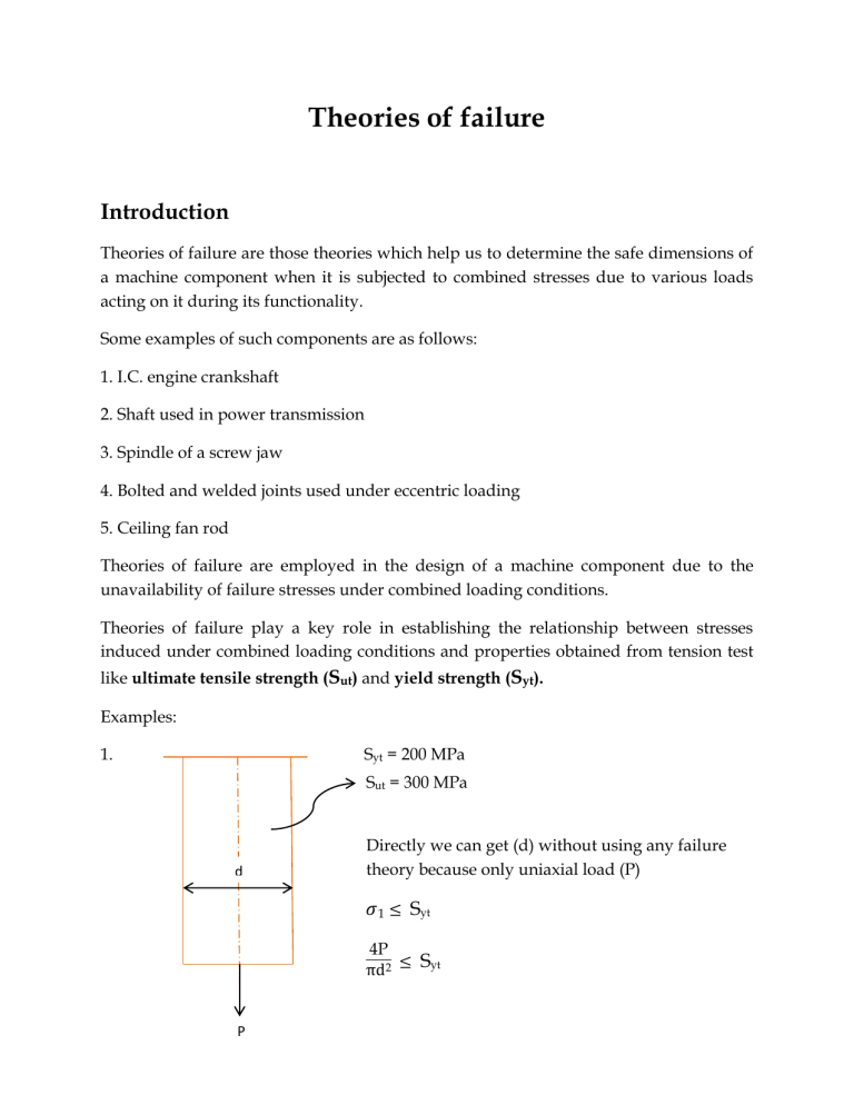
Theories of failure Introduction Theories of failure are those theories which help us to determine the safe dimensions of a machine component when it is subjected to combined stresses due to various loads acting on it during its functionality. Some examples of such components are as follows: 1. I.C. engine crankshaft 2. Shaft used in power transmission 3. Spindle of a screw jaw 4. Bolted and welded joints used under eccentric loading 5. Ceiling fan rod Theories of failure are employed in the design of a machine component due to the unavailability of failure stresses under combined loading conditions. Theories of failure play a key role in establishing the relationship between stresses induced under combined loading conditions and properties obtained from tension test like ultimate tensile strength (Sut) and yield strength (Syt). Examples: 1. Syt = 200 MPa Sut = 300 MPa d Directly we can get (d) without using any failure theory because only uniaxial load (P) 𝜎1 ≤ Syt 4P πd2 ≤ Syt P 2. Member is subjected to both Twisting moment and uniaxial load, hence combined loading conditions. We cannot determine (d) directly in this case because failure stresses under combined loading conditions are unknown. d T P So, different scientists give relationships between Stresses induced under combined loading conditions and (Syt and Sut) obtained using tension test which are called theories of failure. Various Theories of Failure 1. Maximum Principal Stress theory also known as RANKINE’S THEORY 2. Maximum Shear Stress theory or GUEST AND TRESCA’S THEORY 3. Maximum Principal Strain theory also known as St. VENANT’S THEORY 4. Total Strain Energy theory or HAIGH’S THEORY 5. Maximum Distortion Energy theory or VONMISES AND HENCKY’S THEORY 1. Maximum Principal Stress theory (M.P.S.T) According to M.P.S. T Condition for failure is, Maximum principal stress ( 1) failure stresses (Syt or Sut ) and Factor of safety (F.O.S) = 1 If 1 is 1 +ve then Syt or Sut is –ve then Syc or Suc Condition for safe design, Factor of safety (F.O.S) > 1 Maximum principal stress ( 1) ≤ Permissible stress ( per) Syt Sut Failure stress where permissible stress = Factor of safety = N or N 1 Syt Sut ≤ N or N Eqn (1) Note: 1. This theory is suitable for the safe design of machine components made of brittle materials under all loading conditions (tri-axial, biaxial etc.) because brittle materials are weak in tension. 2. This theory is not suitable for the safe design of machine components made of ductile materials because ductile materials are weak in shear. 3. This theory can be suitable for the safe design of machine components made of ductile materials under following state of stress conditions. (i) Uniaxial state of stress (Absolute max = 1 2 ) (ii) Biaxial state of stress when principal stresses are like in nature (Absolute (iii) Under hydrostatic stress condition (shear stress in all the planes is zero). max = 1 2 ) 2. Maximum Shear Stress theory (M.S.S.T) Condition for failure, Maximum shear stress induced at a critical point under triaxial combined stress Yield strength in shear under tensile test Syt (Sys)T.T or 2 Absolute max unknown therefore use Syt Condition for safe design, Maximum shear stress induced at a critical tensile point under triaxial combined stress ≤ Permissible shear stress (τper) where, Permissible shear stress = Absolute max ≤ (Sys)T.T Syt Yield strength in shear under tension test = = N Factor of safety 2N (Sys)T.T N or Syt 2N For tri-axial state of stress, σ3 - σ1 larger of [| σ1 2- σ2 |, |σ2 2- σ3 |, | larger of [ |σ1 – σ2|, | σ2 – σ3|, | σ3 – σ1|] For Biaxial state of stress, σ3 = 0 σ σ1 - σ2 | 21 | or | 2 |≤ Syt 2N 2 |] ≤ ≤ Syt 2N Syt N |σ1| ≤ |σ1 – σ2| ≤ Syt when σ1, σ2 are like in nature N Syt when σ1, σ2 are unlike in nature N Eqn (2) Eqn (3) Note: 1. M.S.S.T and M.P.S.T will give same results for ductile materials under uniaxial state of stress and biaxial state of stress when principal stresses are like in nature. 2. M.S.S.T is not suitable under hydrostatic stress condition. 3. This theory is suitable for ductile materials and gives oversafe design i.e. safe and uneconomic design. 3. Maximum Principal Strain theory (M.P.St.T) Condition for failure, Maximum Principal strain (ε1) ε1 (ε Y.P.)T.T Yielding strain under tensile test (ε Y.P.)T.T Syt or E where E is Young’s Modulus of Elasticity Condition for safe design, Maximum Principal strain ≤ Permissible strain where Permissible strain = ε1 Syt ≤ EN Syt 1 E [σ1 - µ(σ2 + σ3)] ≤ EN Yielding strain under tensile test (ε Y.P.)T.T Syt = = EN Factor of safety N Syt σ1 - µ(σ2 + σ3) ≤ N for biaxial state of stress, σ3 = 0 Syt σ1 - µ(σ2) ≤ N 4. Eqn (4) Total Strain Energy theory (T.St.E.T) Condition for failure, Total Strain Energy per unit volume (T.S.E. /vol) Strain energy per unit volume at yield point under tension test (S.E /vol) Y.P.] T.T Condition for safe design, Total Strain Energy per unit volume ≤ Strain energy per unit volume at yield point under tension test. Eqn (5) σE.L Strain energy per unit volume up 1 to Elastic limit (E.L) = 2 σE.L εE.L εE.L 1 1 1 Total Strain Energy per unit volume = 2 σ1 ε1 + 2 σ2 ε2 + 2 σ3 ε3 (triaxial) Eqn (6) ε1 1 = E [σ1 - µ(σ2 + σ3)] ε2 1 = E [σ2 - µ(σ1 + σ3)] ε3 1 = E [σ3 - µ(σ1 + σ2)] Eqn (7) By substituting equations (6) in equations (5) 1 T.S.E. /vol = 2E [σ12 + σ22 + σ32 - 2µ (σ1 σ2 + σ2 σ3 +σ3 σ1)] (8) To get [(S.E /vol) Y.P.] T.T , Syt Substitute σ1 = σ = N , σ2 = σ3 = 0 in equation (8) 1 Syt [(S.E /vol) Y.P.] T.T = 2E ( N )^2 (9) By Substituting equations (8) and (9) in equation (5), the following equation is obtained Syt σ12 + σ22 + σ32 - 2µ (σ1 σ2 + σ2 σ3 +σ3 σ1) ≤ ( N )^2 for biaxial state of stress, σ3 = 0 Syt σ12 + σ22 - 2µ σ1 σ2 ≤ ( N )^2 (10) Note: 1. Eqn (10) is an equation of ellipse (x2 + y2 - xy = a2). 2. Semi major axis of the ellipse = Semi minor axis of the ellipse = √ √ = = √ √ = 1.2 Syt = 0.87 Syt For µ = 0.3 3. Total strain energy theory is suitable under hydrostatic stress condition. 5. Maximum Distortion Energy Theory (M.D.E.T) Condition for failure, Maximum Distortion Energy/volume (M.D.E/vol) Distortion energy/volume at yield point under tension test (D.E/vol) Y.P.] T.T Condition for safe design, Maximum Distortion Energy/volume ≤ Distortion energy/volume at yield point under tension test (11) T.S.E/vol = Volumetric S.E/vol + D.E/vol D.E/vol = T.S.E/vol - Volumetric S.E /vol Under hydrostatic stress condition, and Under pure shear stress condition, (12) D.E/vol = 0 Volumetric S.E/vol = 0 From equation (8) 1 T.S.E/vol = 2E [σ12 + σ22 + σ32 - 2µ (σ1 σ2 + σ2 σ3 +σ3 σ1)] 1 Volumetric S.E/vol = 2 (Average stress) (Volumetric strain) 1 σ1 + σ2 + σ3 = 2( 3 ) [( 1-2µ E ) (σ1 + σ2 + σ3) ] 1-2µ Vol S.E/vol = 6E (σ1 + σ2 + σ3)2 (13) From equation (12) and (13) 1+µ D.E/vol = 6E [(σ1 - σ2)2 + (σ2 - σ3)2 + (σ3 - σ1)2] To get [(D.E/vol) Y.P.] T.T , Syt Substitute σ1 = σ = N , σ2 = σ3 = 0 in equation (14) (14) 1+µ Syt [(D.E/vol) Y.P.] T.T = 3E ( N )^2 (15) Substituting equation (14) and (15) in the condition for safe design , the following equation is obtained [(σ1 - σ2)2 + (σ2 - σ3)2 + (σ3 - σ1)2] Syt ≤ 2 ( N )^2 For biaxial state of stress, σ3 = 0 S σ1 2 + σ22 – σ1 σ2 ≤ ( Nyt ) ^2 (16) Note: 1. Equation (16) is an equation of ellipse. 2. Semi major axis of the ellipse = √ Syt Semi minor axis of the ellipse = √ Syt 3. This theory is best theory of failure for ductile material. It gives safe and economic design. 4. This theory is not suitable under hydrostatic stress condition. SYS Ration of S by using theories of failure Yt 1. Sys (Yield strength in shear) is obtained from torsion test. 2. Torsion test is conducted under pure torsion i.e. pure shear state of stress (σx = σy= 0; τxy = τ ). 3. Under pure shear state of stress 16T σ1 = τ , σ2 = - τ and τ = d3 4. Sys can also be obtained by applying theories of failure for pure shear state of stress condition. 5. When yielding in shear occurs under pure shear state of stress, τ = Sys. SYS (a) S in Maximum Principal stress theory Yt According to M.P.S.T, Considering Factor of safety (N) = 1 σ1 ≤ Syt σ1 or Syt But in pure shear state of stress, σ1 = τ τ = Syt When yielding occurs in shear under pure shear state of stress, τ = Sys Sys = Syt SYS SYt = 1 SYS (b) S in Maximum shear stress theory Yt According to M.S.S.T, |σ1 – σ2| ≤ Syt But in pure shear state of stress, σ1 = τ and σ2 = -τ τ – (-τ) = Syt 2 τ = Syt When yielding occurs in shear under pure shear state of stress, τ = Sys SYS 1 SYt = 2 SYS (c) S in Maximum principal strain theory Yt According to M.P.St.T, σ1 - µ(σ2) τ - µ(-τ) Syt Syt τ(1+ µ) = Syt Sys = Syt 1+ µ for µ = 0.3 SYS SYt = 0.77 SYS (d) S in Total strain energy theory Yt According to T.St.E.T, σ12 + σ22 - 2µ σ1 σ2 Syt2 τ2 + τ2 + 2 τ2 = Syt2 τ= √ Sys = √ for µ = 0.3 SYS = 0.62 SYt SYS (d) S in Maximum distortion energy theory Yt According to M.D.E.T, σ1 2 + σ22 – σ1 σ2 Syt2 τ2 + τ2 + τ2 = Syt2 τ= √ Sys = √ SYS SYt = 0.577 Equivalent Bending Moment (Me) and Twisting Moment (Te) equations These equations should be used when the component is subjected to both Bending Moment and Twisting Moment simultaneously. T T M M d T.O.F M.P.S.T M.S.S.T M.D.E.T Me and Te Equations Me = 1 [ M + √ 2 Te = √ Me = √ ] = 32 d3 σper = 16 d3 τper = 32 d3 σper Normal Stress Equations (σt equations) Normal stress equations should be used when a point in a component is subjected to normal stress in one direction only and a shear stress. τxy σx σx τxy σt equations T.O.F M.P.S.T σt = 1 [σx + √ 2 Syt ] = N Syt M.S.S.T σt = √ = N M.D.E.T σt = √ = N Syt Shape of safe boundaries for theories of failure Graphical representation or safe boundaries are used to check whether the given dimensions of a component are safe or not under given loading conditions. As per theories of failure for ductile material, Syc = - Syt (a) M.P.S.T :- Square σ2 Syt -σ1 Syc Syt σ1 Syc = -Syt -σ2 (b) M.S.S.T :- Hexagon σ2 σ1 -σ2 = -Syt -σ1 σ1 σ1 -σ2 = Syt -σ2 (c) M.P.St.T :- Rhombus σ2 Syt - σ1 σ1 -Syt Syt -Syt -σ2 (c) M.D.E.T :- Ellipse σ2 M.D.E.T Syt M.S.S.T -Syt -σ1 σ1 Syt -Syt - σ2 Note :1. Semi major axis of the ellipse = Syt √ Semi minor axis of the ellipse = √ Syt 2. As the area bounded by the curve increases, failure stresses increases thereby decreases dimensions and hence cost of safety. In all the quadrants Area bounded by the MDET curve Aread bounded by MSST curve Hence (Dimensions)MDET (Dimensions)MSST (c) T.St.E.T :- Ellipse σ2 Syt -Syt -σ1 Syc Syt Syc = -Syt - σ2 σ1 Syt Note: Semi- major axis of the ellipse = Semi- minor axis of the ellipse = √ √ For Objective Questions 1. All the theories of the failure will give the same result when uniaxial state of stress Examples – 1. Bar subjected to uniaxial load 2. Beam subjected to pure bending 2. All the theories of the failure will give the same result when one of the principal stresses is very large as compared to the other principal stresses. 3. For pure shear state of stress, all the theories of failure will give the different result. (a) MDET and MSST will be used under pure shear state of stress. (b) MDET will be preferred over MSST. 4. MSST and MDET are not valid for hydrostatic state of stress condition. 5. TSET and MPST will be used for hydrostatic state of stress condition. TSET will be preferred over MPST. References 1. Introduction to Machine Design by V.B Bhandari 2. NPTEL content and Videos
