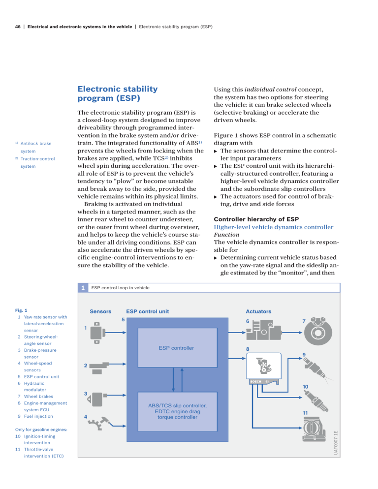
46 | Electrical and electronic systems in the vehicle | Electronic stability program (ESP) Electronic stability program (ESP) 1) Antilock brake system 2) Traction-control system The electronic stability program (ESP) is a closed-loop system designed to improve driveability through programmed intervention in the brake system and/or drivetrain. The integrated functionality of ABS1) prevents the wheels from locking when the brakes are applied, while TCS2) inhibits wheel spin during acceleration. The overall role of ESP is to prevent the vehicle’s tendency to “plow” or become unstable and break away to the side, provided the vehicle remains within its physical limits. Braking is activated on individual wheels in a targeted manner, such as the inner rear wheel to counter understeer, or the outer front wheel during oversteer, and helps to keep the vehicle’s course stable under all driving conditions. ESP can also accelerate the driven wheels by specific engine-control interventions to ensure the stability of the vehicle. 1 1 Yaw-rate sensor with lateral-acceleration sensor Figure 1 shows ESP control in a schematic diagram with ▶ The sensors that determine the controller input parameters ▶ The ESP control unit with its hierarchically-structured controller, featuring a higher-level vehicle dynamics controller and the subordinate slip controllers ▶ The actuators used for control of braking, drive and side forces Controller hierarchy of ESP Higher-level vehicle dynamics controller Function The vehicle dynamics controller is responsible for ▶ Determining current vehicle status based on the yaw-rate signal and the sideslip angle estimated by the “monitor”, and then ESP control loop in vehicle Sensors Fig. 1 Using this individual control concept, the system has two options for steering the vehicle: it can brake selected wheels (selective braking) or accelerate the driven wheels. ESP control unit 5 Actuators 6 7 1 2 Steering-wheelangle sensor ESP controller 3 Brake-pressure sensor 4 Wheel-speed sensors 8 9 2 5 ESP control unit 6 Hydraulic 7 Wheel brakes 10 3 8 Engine-management system ECU 9 Fuel injection Only for gasoline engines: 10 Ignition-timing intervention 11 Throttle-valve intervention (ETC) 4 ABS/TCS slip controller, EDTC engine drag torque controller 11 UAF0007-1E modulator Electrical and electronic systems in the vehicle | Electronic stability program (ESP) | 47 ▶ achieving maximum possible convergence between vehicle response in the limit range and its characteristics in the normal operating range (nominal behavior). The following components register driver commands and the system evaluates their signals as the basis for defining nominal behavior: ▶ Engine-management system (e.g. apply accelerator pedal) ▶ Brake-pressure sensor (e.g. apply brakes) or ▶ Steering-wheel-angle sensor (turning the steering wheel) At this point the driver command is defined as the specified response. The coefficient of friction and the vehicle speed are also included in the calculation. The “monitor” estimates these factors based on signals transmitted by the sensors for ▶ Wheel speed ▶ Lateral acceleration ▶ Braking pressures and ▶ Yaw velocity The desired vehicle response is brought about by generating a yaw moment acting on the vehicle. In order to generate the desired yaw moment, the system influences the tire-slip rate, and thus indirectly the longitudinal and side forces. The system influences the tire slip by varying the desired specifications for slip rate, which must then be executed by the subordinated ABS and TCS controllers. The intervention process is designed to maintain the handling characteristics that the vehicle manufacturer intended the vehicle to have and to serve as the basis for ensuring consistently reliable control. The vehicle dynamics controller generates the specified yaw moment by relaying corresponding slip-modulation commands to the selected wheels. The subordinate-level ABS and TCS controllers trigger the actuators governing the brake hydraulics and the engine-management system using the data generated in the ESP controller. Antilock brake system (ABS) The antilock brake system (ABS) detects incipient lock on one or more wheels and makes sure that the brake pressure remains constant or is reduced. By so doing, it prevents the wheels from locking up and the vehicle remains steerable. Wheel-speed sensors The speed of rotation of the wheels is an important input variable for the ABS control system. Wheel-speed sensors detect the speed of rotation of the wheels and pass the electrical signals to the control unit. A car may have three or four wheelspeed sensors depending on which version of the ABS system is fitted (ABS system versions). The speed signals are used to calculate the degree of slip between the wheels and the road surface and therefore detect incipient lock on individual wheels. Electronic control unit The ECU processes the information received from the sensors according to defined mathematical procedures (control algorithms). The results of these calculations form the basis for the triggering signals sent to the hydraulic modulator. Hydraulic modulator The hydraulic modulator incorporates a series of solenoid valves that can open or close the hydraulic circuits between the master cylinder (Fig. 2, Item 1) and the wheel-brake cylinders (4). In addition, it can connect the wheel-brake cylinders to the return pump (6). Solenoid valves with two hydraulic connections and two valve positions are used (2/2 solenoid valves). 48 | Electrical and electronic systems in the vehicle | Electronic stability program (ESP) Fig. 2 1 Master cylinder with expansion tank 2 Brake booster 3 Brake pedal 4 Wheel brake with wheel-brake cylinder The intake valve (7) between the master cylinder and the wheel-brake cylinder controls pressure build-up, while the exhaust valve (8) between the wheel-brake cylinder and the return pump controls pressure release. There is one such pair of solenoid valves for each wheel-brake cylinder. Under normal conditions, the solenoid valves in the hydraulic modulator are at the “pressure build-up” setting. That means the intake valve is open. The hydraulic modulator then forms a straightthrough connection between the master cylinder and the wheel-brake cylinders. Consequently, the brake pressure generated in the master cylinder when the brakes are applied is transmitted directly to the wheel-brake cylinders at each wheel. As the degree of brake slip increases due to braking on a slippery surface or panic braking, the risk of the wheels locking up also increases. The solenoid valves are then switched to the “maintain pres- sure” setting. The connection between the master cylinder and the wheel-brake cylinder is shut off (intake valve is closed) so that any increase of pressure in the master cylinder does not lead to an increase in brake pressure. If the degree of slip of any of the wheels increases further despite this action, the pressure in the wheel-brake cylinder(s) concerned must be reduced. To achieve this, the solenoid valves are switched to the “pressure release” setting. The intake valve is still closed, and in addition, the exhaust valve opens to allow the return pump integrated in the hydraulic modulator to draw brake fluid from the brake(s) concerned in a controlled manner. The brake pressure in the wheel-brake cylinder is thus reduced so that wheel lock-up does not occur. ABS control loop Overview The ABS control loop (Fig. 3) consists of the following: Hydraulic modulator with 5 Damping chamber 6 Return pump 7 Intake valve 8 Exhaust valve 9 Brake-fluid accumulator 2 Principle of hydraulic modulator with 2/2 solenoid valves (schematic) 1 3 ABS control loop 2 5 ABS ECU 3 Calculate (actual slip) Controlled variable Intake valve: shown in open Regulate (required slip) setting 6 Monitor Exhaust valve: setting 6 7 Hydraulic modulator with solenoid valves Act on brake pressure 5 Fig. 3 1 Brake pedal 2 Brake booster 3 Master cylinder with expansion tank Wheel-speed sensor 6 9 4 Warning lamp Correcting variable Disturbance values (e.g. road condition) Wheel-brake cylinder 5 Controlled system UFB0701Y 4 4 8 Build up brake pressure 3 Pedal force 2 1 UFB0689-1E shown in closed Electrical and electronic systems in the vehicle | Electronic stability program (ESP) | 49 The disturbance values affecting the control loop ▶ Changes in the frictional connection between the tires and the road surface caused by different types of road surface and changes in wheel load, e.g. when cornering ▶ Irregularities in the road surface causing the wheels and axles to vibrate ▶ Lack of circularity of the tires, low tire pressure, worn tire tread, differences in circumference between wheels, (e.g. spare wheel) ▶ Brake hysteresis and fade ▶ Differences in master-cylinder pressure between the two brake circuits Controller ▶ The wheel-speed sensors ▶ The ABS control unit Controlled variables ▶ Wheel speed and, derived from it, wheel deceleration ▶ Wheel acceleration and brake slip The reference variable The foot pressure applied to the brake pedal by the driver – amplified by the brake booster – generates the brake pressure in the brake system ▶ The correcting variable ▶ Brake pressure in the wheel-brake cylinder ▶ An idealized coefficient of friction slip curve (substitute for the friction pairing of tire and road) That curve is divided into a stable zone with a linear gradient and an unstable zone with a constant progression (µHFmax). As an additional simplification, there is also an assumed initial straight-line braking response that is equivalent to a panicbraking reaction. Figure 4 shows the relationships between brake torque MB (the torque that can be generated by the brake through the tire), or road frictional torque MR (torque that acts against the wheel through the friction pairing of tire and road surface), and time t, as well as the relationships between the wheel deceleration (–a) and time t, whereby the brake torque increases in linear fashion over time. The road frictional torque lags slightly behind the brake torque by the time delay T, as long as the braking sequence is within the stable zone 4 Initial braking phase, simplified MB Road frictional torque MR Brake torque MB Controlled system The vehicle and its wheel brakes ▶ The wheels and the friction pairing of tire and road surface ▶ MB – MR MRmax T MR Fig. 4 (–a) Wheel deceleration Wheel deceleration –a (–amax) Maximum wheel deceleration –amax 0 100 200 Time t ms UFB0363-2E Controlled system The data-processing operations performed by the ABS control unit are based on the following simplified controlled system: ▶ A non-driven wheel ▶ A quarter of the vehicle’s mass apportioned to that wheel ▶ Wheel brake MB Brake torque MR Road frictional torque MRmax Maximum road frictional torque T Time delay 50 | Electrical and electronic systems in the vehicle | Electronic stability program (ESP) of the curve for coefficient of friction versus brake slip. After about 130 ms, the maximum level (µHFmax) – and therefore the unstable zone – of the curve for coefficient of friction versus brake slip is reached. From that point on, the curve for coefficient of friction versus brake slip states that while the brake torque MB, continues to rise at an undiminished rate, the road frictional torque MR, cannot increase any further and remains constant. In the period between 130 and 240 ms (this is when the wheel locks up), the minimal torque difference MB – MR, that was present in the stable zone rises rapidly to a high figure. That torque difference is a precise measure of the wheel deceleration (–a) of the braked wheel (Fig. 4, bottom). In the stable zone, the wheel deceleration is limited to a small rate, whereas in the unstable zone it increases rapidly, according to the amount. As a consequence, the curve for coefficient of friction versus wheel slip reveals opposite characteristics in the stable and unstable zones. The ABS exploits these opposing characteristics. Controlled variables An essential factor in determining the effectiveness of an ABS control system is the choice of controlled variables. The basis for that choice is the wheel-speed sensor signals from which the ECU calculates the deceleration/acceleration of the wheel, brake slip, the reference speed and the vehicle deceleration. On their own, neither the wheel deceleration/acceleration nor the brake slip are suitable as controlled variables because, under braking, a driven wheel behaves entirely differently to a non-driven wheel. However, by combining those variables on the basis of appropriate logical relationships, good results can be obtained. As brake slip is not directly measurable, the ECU calculates a quantity that approximates to it. The basis for the calculation is the reference speed, which represents the speed under ideal braking conditions (optimum degree of brake slip). So that speed can be determined, the wheel-speed sensors continuously transmit signals to the ECU for calculating the speed of the wheels. The ECU takes the signals from a pair of diagonally opposed wheels (e.g. right front and left rear) and calculates the reference speed from them. Under partial braking, the faster of the two diagonally opposite wheels generally determines the reference speed. If the ABS cuts in under emergency braking, the wheel speeds will be different from the vehicle speed and can thus not be used for calculating the reference speed without adjustment. During the ABS control sequence, the ECU provides the reference speed based on the speed at the start of the control sequence and reduces it at a linear rate. The gradient of the referencespeed graph is determined by analyzing logical signals and relationships. If, in addition to the wheel acceleration/ deceleration and the brake slip, the vehicle deceleration is brought into the equation as an additional quantity, and if the logical circuit in the ECU is modulated by computation results, then ideal brake control can be achieved. This concept has been realized in the Bosch antilock brake system (ABS). Traction-control system (TCS) The antilock brake system (ABS) prevents the wheel lock when the brakes are applied by lowering the wheel brake pressures. The traction-control system (TCS) prevents wheel spin by reducing the drive torque at each driven wheel. In addition to this safety-relevant task of ensuring the stability and steerability of the vehicle when accelerating, TCS also improves the traction of the vehicle by regulating the optimum slip. The upper limit here is, of course, set by the traction requirement stipulated by the driver. The TCS regulates the slip of the driven wheels as quickly as possible to the optimum level. To do this the system first de- Electrical and electronic systems in the vehicle | Electronic stability program (ESP) | 51 termines a setpoint value for the slip. This value depends on a number of factors that represent the current driving situation. These factors include: ▶ The basic characteristic for TCS reference slip (based on the slip requirement of a tire during acceleration) ▶ Effective coefficient of friction ▶ External tractive resistance (deep snow, rough road, etc.) ▶ Yaw velocity, lateral acceleration, and steering angle of the vehicle TCS interventions The measured wheel speeds and the respective drive slip can be influenced by changing the torque balance Mtot at each drive wheel. The torque balance Mtot at each driven wheel results from the drive torque MKar/2 at this wheel, the respective brake torque MBr and the road torque MStr (Fig. 5). Mtot = MKar /2 + MBr + MStr (MBr and MStr are negative here.) Both these parameters are therefore correcting variables of the TCS which can be used to regulate the slip at each wheel to the reference slip level. In gasoline-engine vehicles, the drive torque MKar can be controlled using the following engine-control interventions: ▶ Throttle valve (throttle valve adjustment) ▶ Ignition system (ignition-timing advance) ▶ Fuel-injection system (phasing out individual injection pulses) In diesel-engine vehicles, the drive torque MKar is influenced by the electronic diesel control system (EDC) (reduction in the injected fuel quantity). The brake torque MBr can be regulated for each wheel via the brake system. The TCS function requires the original ABS hydraulic system to be expanded because of the need for active pressure build-up. This balance can obviously by influenced by the drive torque MKar provided by the engine as well as by the brake torque MBr. Fig. 5 1 Engine with 2 Wheel transmission Drive concept of a single-axle driven vehicle with TCS 3 Wheel brake 4 Transversal 5 Electronic control differential 5&" unit with TCS functionality 62 (2 -3TR 2 -"R 2 X2 Engine, transmission, gear ratio of differential -2 -+AR -+AR X+AR and losses are combined in one unit. -, -+AR X, %NGINEINTERVENTION 6, MKar Drive axle torque vKar Cardan speed -3TR , -"R , (, MBr Brake torque MStr Torque transferred to the road UFB0757E 5 v Wheel speed R Right L Left V Front H Rear 52 | ABS versions ▶ ABS versions ▶ Sensor and relay technology have enabled Evolution of the ABS versions Technological advances in the areas of the weight and dimensions of ABS versions ▶ Solenoid-valve design and manufacturing. to be more than halved since the first-gen- ▶ Assembly and component integration. eration ABS2 in 1978. As a result, modern ▶ Electronic circuitry (discrete components systems can now be accommodated even replaced by hybrid and integrated circuits in vehicles with the tightest space restric- with microcontrollers). tions. Those advances have also lowered ▶ Testing methods and equipment (separate the cost of ABS systems to the extent that testing of electronic and hydraulic systems they are now fitted as standard on all types before integration in the hydraulic modulator). of vehicle. 1 Evolution of ABS configurations Hydraulic-modulator development ABS 2 ABS 5.0 Weight ABS 5.3/5.7 6,200 g ABS 8 3,800 g 2,600 g < 2,000 g Development of electronics ABS 2 ABS 5.0 ABS 5.3 1989 1993 1995 ABS 5.3/5.7 ABS 8 Fig. 1 Historical development technological advances: Decreasing weight accompanied by increasing processing power. 2001 UFB0700E of ABS showing ElectrHistory of radar | 53 History of radar Technology to mimic the animals While air travel and shipping radar systems, Radar (RAdiation Detecting And Ranging) is for example, operate in the 500 MHz to 40 GHz a wireless method for locating objects that frequency range, ACC is authorized to use the has traditionally been used mainly in air travel 76 to 77 GHz frequency band. and shipping. Since radar-supported air defence was introduced in World War 2, radar Stages in the development of radar has also been a feature of weapons technol- The development of electromagnetic, long- ogy. More recently, radar has found applica- range search facilities was a great challenge tion in space travel, weather forecasting and for design engineers. Only a small part of the ultimately in road traffic as part of measuring energy originally emitted was reflected back. distances between vehicles using ACC It is therefore necessary to emit a large (Adaptive Cruise Control). amount of energy and to concentrate it in as narrow a beam bundle as possible. The only The basis for the development of radar was devices suitable for this are very sensitive the sonar system (Sound Navigation and Rang- transmitters and receivers for waves that are ing) possessed by animals for navigation and shorter than the dimensions of the target. determining distances. Echolocating bats, for The development path that led to radar example, emit orientation sounds in the form technology is punctuated by the following his- of shrill whistles in the 30 to 120 kHz ultra- torical milestones and characters: sound range. They then pick up the echo 1837 Morse: Message transmission over long from obstacles or their prey with their ears. distances by means of electrical pulses They use the information contained in the sent by the telegraph was the first echo to decide what to do next. method to find widespread use 1861/1876 Reis and Bell: Replacement of telegraphs by the telephone makes message transfer much more direct and user-friendly 1864 Maxwell, Hertz and Marconi: Existence of “radio waves” proven theoretically and experimentally. Radio waves reflect off metallic objects in the same way as light waves reflect off a mirror 1922 Marconi: The pioneer of the radio proposes further investigations into earlier research approaches to radio measuring technology UFS0038Y ▶ 1925 Appleton and Barnett: The principle of radio measuring technology is used to detect conducting strata in the atmosphere Radar functions in a similar way but uses Breit and Tuve: Development of pulse radio signals not sound waves. The distance modulation that permits exact develop- measurement method of radar is based on ment measurements the measurement of the time that elapses 1935 Watson Watt: Invention of the radar between the emission of the electromagnetic 1938 Ponte: Invention of the magnetron waves and the reception of a signal echo re- (velocity-modulated tube for generating flected by an object. high-frequency vibrations)


