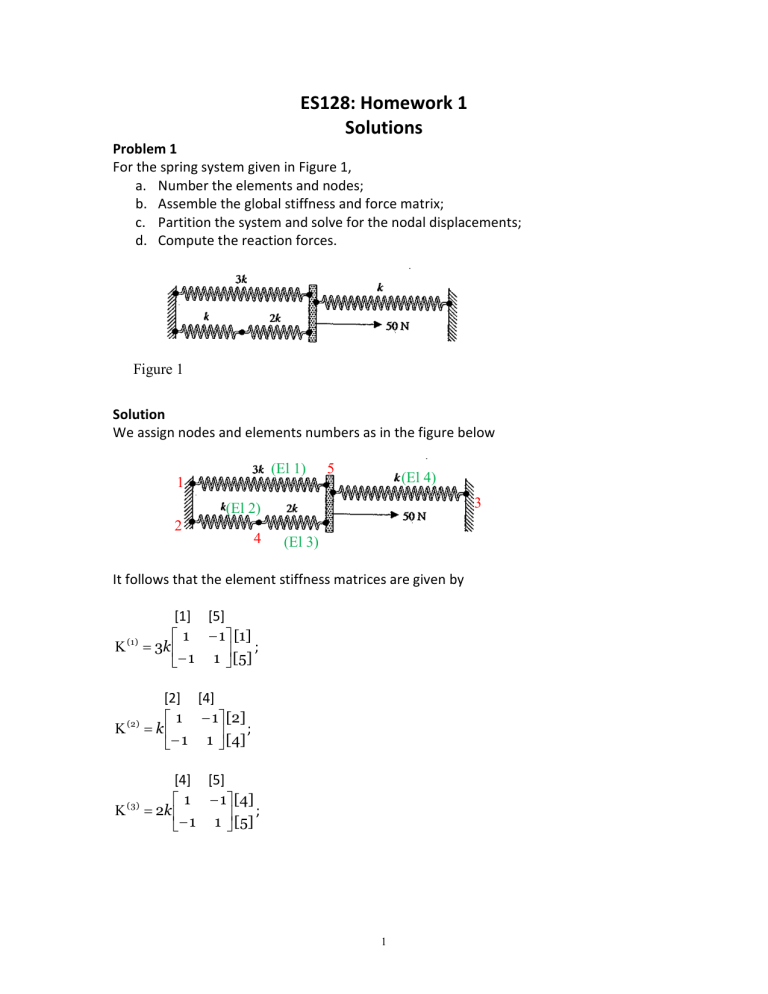
ES128: Homework 1 Solutions Problem 1 For the spring system given in Figure 1, a. Number the elements and nodes; b. Assemble the global stiffness and force matrix; c. Partition the system and solve for the nodal displacements; d. Compute the reaction forces. Figure 1 Solution We assign nodes and elements numbers as in the figure below (El 1) 5 (El 4) 1 3 (El 2) 2 4 (El 3) It follows that the element stiffness matrices are given by Κ (1) [1] [5] 1 − 1 [1] = 3k ; − 1 1 [ 5] Κ (2) [2] [4] 1 − 1 [2] = k ; − 1 1 [4] Κ ( 3) [4] [5] 1 − 1 [ 4] = 2k ; − 1 1 [ 5] 1 Κ ( 4) [5] [3] 1 − 1 [ 5] = k . − 1 1 [3] The global stiffness matrix is given by [1] [2] [3] [4] [5] 0 0 0 − 3 [1] 3 0 1 0 − 1 0 [2] Κ = k 0 0 1 0 − 1 [3] . 3 − 2 [4] 0 −1 0 − 3 0 − 1 − 2 6 [5] The displacement and force nodal vectors are 0 r1 0 r 2 0 , f = r3 . d= u4 0 u5 50 To impose the prescribed boundary conditions, we partition the system as K EE K FE K EF d E f E , = K FF d F f F 0 − 3 0 3 0 0 3 − 2 where K EE = k 0 1 0 ; K EF = k − 1 0 ; K FF = k ; d E = 0 ; − 2 6 0 − 1 0 0 0 1 r1 u 4 0 d F = ; f E = r2 ; and f F = . 50 u5 r3 Since d E = [ 0 0 0], K FF d F = f F , so that 1 d F = K -FF fF = 1 7.1429 . k 10.7143 2 Therefore, u 4 = 7.1429 / k and u5 = 10.7143 / k. Since d E = [0 0 0], K EF d F = f E , so that − 32.1429 f E = K EF d F = − 7.1429 . − 10.7143 Therefore, r1 = −32.1429 (N), r2 = −7.1429 (N) and r3 = −10.7143 (N). Problem 2 Figure 2 shows a two-member plane truss supported by a linearly elastic spring. The truss members are of a solid circular cross section having d=20 mm and E=80Gpa. The linear spring has stiffness constant 50 N/mm. a. Assemble the system global stiffness matrix and calculate the global displacements of the unconstrained node; b. Compute the reaction forces and check the equilibrium conditions; c. Check the energy balance. Is the strain energy in balance with the mechanical work of the applied force? d. Compute the strain and stress in each bar. Figure 2 3 Solution We assign nodes and elements numbers as in the figure below 1 (El 1) 4 (El 2) 2 (El 3) 3 For element 1 80 × 10 9 × EA = l1 sin φ 1 = −3 / 5 k1 = π 4 × (20 × 10 −3 )2 5 = 5.0265 × 10 6 ( N / m) ; cos φ 1 = 4 / 5 [1x] [1y] [4x] [4y] − 2.4127 − 3.217 2.4127 [1 x ] 3.217 − 2.4127 1.8095 2.4127 − 1.8095 [1 y] Κ (1 ) = 10 6 − 3.217 2.4127 3.217 − 2.4127 [4 x ] 2.4127 − 1.8095 − 2.4127 1.8095 [4y] For element 2 EA = l2 sin φ 2 = 0 k2 = 80 × 10 9 × π 4 × (20 × 10 −3 )2 4 = 6.2832 × 10 6 ( N / m ) ; cos φ 2 = 1 Κ (2) [2x] [2y] [4x] [4y] 6.2832 0 − 6.2832 0 0 0 6 = 10 − 6.2832 0 6.2832 0 0 0 0 [2 x ] 0 [2 y] 0 [ 4 x ] 0 [ 4 y ] 4 For element 3 k 3 = 50 × 10 3 ( N / m ) ; sin φ 3 = 1 ; cos φ 3 = 0 ; [3x] [3y] 0 0 0 0.05 Κ ( 3) = 10 6 0 0 0 − 0.05 [4x] [4y] 0 0 [3 x ] 0 − 0.05 [3y] 0 0 [4 x ] 0 0.05 [4y] The global stiffness matrix is [1x] [1y] [2x] 0 − 2.4127 3.217 − 2.4127 1.8095 0 0 0 6.2832 0 0 0 Κ = 10 6 0 0 0 0 0 0 − 3.217 2.4127 − 6.2832 0 2.4127 − 1.8095 [2y][3x] [3y] 0 0 0 0 0 0 0 0 0 0 0 0 0 0 0 0 0 0 [4x] − 3.217 2.4127 [4y] 2.4127 [1 x ] − 1.8095 [1 y] [2 x ] 0 0 − 6.2832 0 0 0 [2 y ] . [3 x ] 0 0 0 0.05 0 − 0.05 [3y] 0 9.5002 − 2.4127 [4 x ] − 0.05 − 2.4127 1.8595 [4 y] The displacement and force matrices are 0 r1x r1x 0 r1 y r1 y 0 r2 x r2 x 0 r2 y r2 y . d= ; f = = 0 r3 x r3 x r3 y r3 y 0 3 o 3 u 15 × 10 × cos 50 9.6418 × 10 4x 3 0 3 u4 y 15 × 10 × sin 50 11.4907 ×10 To impose the prescribed boundary conditions, we partition the system as K EE K T EF K EF d E f E = , K FF d F f F 5 − 2.4127 0 0 0 0 3.217 − 2.4127 1,8095 0 0 0 0 0 0 6.2832 0 0 0 where K EE = 10 6 ; 0 0 0 0 0 0 0 0 0 0 0 0 0 0 0 0 0 0.05 2.4127 − 3.217 0 2.4127 − 1.8095 0 0 − 2.4127 0 6 − 6.2832 6 9.5002 K EF = 10 ; d = ; K FF = 10 E 0 ; 0 0 − 2.4127 1.8595 0 0 0 0 − 0.05 0 r1 x r 1y r2 x u 4 x 9.6418 × 10 3 d F = ; rE = ; f F = . 3 r2 y 11.4907 × 10 u 4 y r3 x r3 y Since d E = [ 0 0 0], K FF d F = f F , so that 3.8543 d F = K -F1f F = 10 −3 ( m) 11.1804 u4 x = 3.8543(mm) u4 y = 11.1804(mm). Since d E = [ 0 0 0], 14.5757 − 10.9317 − 24 . 2175 f E = K EF d F = 10 3 (N). 0 0 − 0.5590 r1 x = 14.5757(kN); r1 y = -10.9317(kN); r2 x = -24.2175 (kN); r2 y = 0 ; 6 r3 x = 0 ; r3 y = -0.5590 (kN). The resultant of the reaction forces in x direction is 14.5757+(-24.2175)+9.6418=0. The resultant of the reaction forces in y direction is (-10.9317)+(-0.5590)+11.4907=0. The strain for element 1 is 4 / 5 ⋅ 3.8543 ⋅10 −3 − 3 / 5 ⋅11.1804 ⋅10 −3 1 ε = = −7.249 ⋅10 − 4 5 The stress for Element 1 is σ 1 = E 1ε 1 = 80 ⋅10 9 ⋅ (−7.249 ⋅10 −4 ) = −58MPa The strain for element 2 is 3.8543 ⋅10 −3 ε1 = = 9.6357 ⋅10 − 4 4 The stress for Element 2 is σ 2 = E 2ε 2 = 80 ⋅10 9 ⋅ (9.6357 ⋅10 −4 ) = 77.1MPa The strain energy for Element 1 is 1 π G1 = σ 1ε 1 d 2 l 1 =33.0201 (J). 2 4 The strain energy for Element 2 is 1 π G2 = σ 2ε 2 d 2 l 2 =46.671 (J). 2 4 The strain energy for the spring is 1 G3 = ku 42 y =3.1250 (J). 2 The strain energy of the system is 82.816 (J) If the work done by the external force is computed assuming the force had remained constant from the initial state to the final state we obtain Mechanical work of the applied force = ( f 4 x u 4 x + f 4 y u 4 y )=2x82.816 (J) In the linear theory of elasticity Clapeyron's theorem states that the potential energy of deformation of a body, which is in equilibrium under a given load, is equal to half the work done by the external forces computed assuming these forces had remained constant from the initial state to the final state 7 In reality the forces increased slowly from the initial state (force=0) to the final state (force= final force). If the work done by the external force is computed assuming the force increased from the initial state to the final state we obtain Mechanical work of the applied force = 0.5( f 4 x u 4 x + f 4 y u 4 y )=82.816 (J) 8


