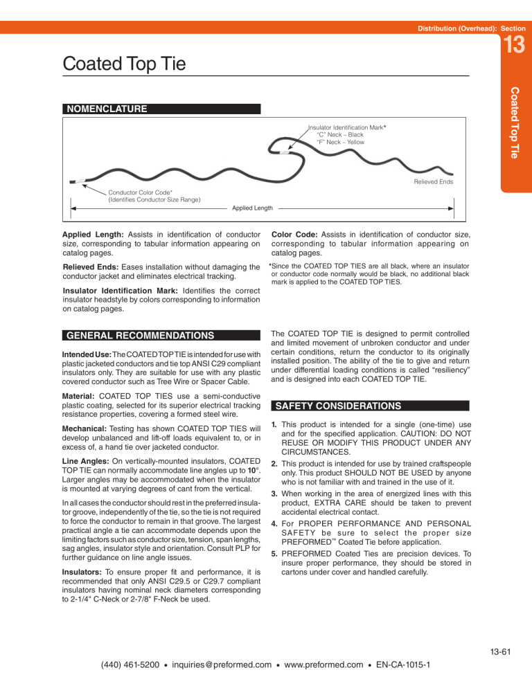
Distribution (Overhead): Section 13 Coated Top Tie Coated Top Tie NOMENCLATURE Insulator Identification Mark* “C” Neck – Black “F” Neck – Yellow Relieved Ends Conductor Color Code* (Identifies Conductor Size Range) Applied Length Applied Length: Assists in identification of conductor size, corresponding to tabular information appearing on catalog pages. Color Code: Assists in identification of conductor size, corresponding to tabular information appearing on catalog pages. Relieved Ends: Eases installation without damaging the conductor jacket and eliminates electrical tracking. *Since the COATED TOP TIES are all black, where an insulator or conductor code normally would be black, no additional black mark is applied to the COATED TOP TIES. Insulator Identification Mark: Identifies the correct insulator headstyle by colors corresponding to information on catalog pages. GENERAL RECOMMENDATIONS Intended Use: The COATED TOP TIE is intended for use with plastic jacketed conductors and tie top ANSI C29 compliant insulators only. They are suitable for use with any plastic covered conductor such as Tree Wire or Spacer Cable. Material: COATED TOP TIES use a semi-conductive plastic coating, selected for its superior electrical tracking resistance properties, covering a formed steel wire. Mechanical: Testing has shown COATED TOP TIES will develop unbalanced and lift-off loads equivalent to, or in excess of, a hand tie over jacketed conductor. Line Angles: On vertically-mounted insulators, COATED TOP TIE can normally accommodate line angles up to 10°. Larger angles may be accommodated when the insulator is mounted at varying degrees of cant from the vertical. In all cases the conductor should rest in the preferred insulator groove, independently of the tie, so the tie is not required to force the conductor to remain in that groove. The largest practical angle a tie can accommodate depends upon the limiting factors such as conductor size, tension, span lengths, sag angles, insulator style and orientation. Consult PLP for further guidance on line angle issues. Insulators: To ensure proper fit and performance, it is recommended that only ANSI C29.5 or C29.7 compliant insulators having nominal neck diameters corresponding to 2-1/4" C-Neck or 2-7/8" F-Neck be used. The COATED TOP TIE is designed to permit controlled and limited movement of unbroken conductor and under certain conditions, return the conductor to its originally installed position. The ability of the tie to give and return under differential loading conditions is called “resiliency” and is designed into each COATED TOP TIE. SAFETY CONSIDERATIONS 1. This product is intended for a single (one-time) use and for the specified application. CAUTION: DO NOT REUSE OR MODIFY THIS PRODUCT UNDER ANY CIRCUMSTANCES. 2. This product is intended for use by trained craftspeople only. This product SHOULD NOT BE USED by anyone who is not familiar with and trained in the use of it. 3. When working in the area of energized lines with this product, EXTRA CARE should be taken to prevent accidental electrical contact. 4. For PROPER PERFORMANCE AND PERSONAL SAFETY be sure to select the proper size PREFORMED™ Coated Tie before application. 5. PREFORMED Coated Ties are precision devices. To insure proper performance, they should be stored in cartons under cover and handled carefully. 13-61 (440) 461-5200 • inquiries@preformed.com • www.preformed.com • EN-CA-1015-1 Coated Top Tie For use on: Plastic Jacket Conductor C-Neck Interchangeable Headstyle Insulators ANSI 55-2 Pin ANSI 55-3 Pin Catalog Number CTC-0201 CTC-0202 CTC-0203 CTC-0204 CTC-0205 CTC-0206 CTC-0207 CTC-0208 CTC-0209 CTC-0210 CTC-0211 CTC-0212 CTC-0213 CTC-0214 2-1/4" Neck Diameter Diameter Range (Inches) Min. .278 .316 .358 .406 .460 .521 .589 .666 .756 .859 .969 1.097 1.241 1.403 Max. .315 .357 .405 .459 .520 .588 .665 .755 .858 .968 1.096 1.240 1.402 1.585 Units Wt./Lbs. Per Carton 100 18 100 19 100 20 50 17 50 17 50 18 50 18 50 19 50 19 50 20 50 21 50 22 50 23 50 24 Applied Length (Inches) 28 28 30 30 32 33 34 36 36 40 44 48 48 48 Insulator Identification Mark Black/None Black/None Black/None Black/None Black/None Black/None Black/None Black/None Black/None Black/None Black/None Black/None Black/None Black/None Color Code Purple Red Yellow Blue Orange Red Purple Brown Red Blue Green Yellow Orange Black/None Applied Length (Inches) 28 28 30 30 32 33 34 36 36 40 44 48 48 48 Insulator Identification Mark Yellow Yellow Yellow Yellow Yellow Yellow Yellow Yellow Yellow Yellow Yellow Yellow Yellow Yellow Color Code Purple Red Yellow Blue Orange Red Purple Brown Red Blue Green Yellow Orange Black/None For use on: Plastic Jacket Conductor F-Neck Interchangeable Headstyle Insulators ANSI 55-4 Pin ANSI 55-5 Pin ANSI 57-1 Post ANSI 57-2 Post ANSI 57-3 Post Catalog Number CTF-0101 CTF-0102 CTF-0103 CTF-0104 CTF-0105 CTF-0106 CTF-0107 CTF-0108 CTF-0109 CTF-0110 CTF-0111 CTF-0112 CTF-0113 CTF-0114 2-7/8" Neck Diameter Diameter Range (Inches) Min. .278 .316 .358 .406 .460 .521 .589 .666 .756 .859 .969 1.097 1.241 1.403 Max. .315 .357 .405 .459 .520 .588 .665 .755 .858 .968 1.096 1.240 1.402 1.585 Units Wt./Lbs. Per Carton 100 20 100 20 100 20 50 18 50 18 50 19 50 19 50 20 50 21 50 22 50 23 50 35 50 26 50 28 13-62 (440) 461-5200 • inquiries@preformed.com • www.preformed.com • EN-CA-1015-1 Insulator Fit Interchangeable Insulators for use with PLP® Ties Dimensional Factors that affect Tie Application and Performance Shoulder Dia. Top Groove to Side Groove Distance 4. 2. Neck Diameter Top Groove Radius Saddle Length 3. 1. Groove Depth Side Groove Radius It is recommended that only insulators meeting the dimensional requirements of the most recent ANSI® C29.3, C29.5, C29.6, and C29.7 specifications be used with the appropriate PLP ties. ANSI C29 Insulator Specifications and their Affects on PLP Ties ANSI C29 specifies and defines dimensions for insulator heads that are crucial to the proper application and lifetime performance of PLP factory formed ties. These dimensions include: • Neck Diameter - nominal - C-neck – 2-1/4" - F-neck – 2-7/8" - J-neck – 3-1/2" - K-neck – 4" • Top groove radius (minimum) • Side groove radius (minimum) • Maximum shoulder diameter (maximum) • Top groove to side groove vertical spacing Some of the specified dimensions are simply maximum or minimum allowable values. The dimensions for the vertical distance from the bottom of the top groove to the middle of the side groove and the neck diameter have minimum and maximum values designated. These dimensions and insulator designations determine the proper tie to be used and the maximum conductor size for the groove application. Review the individual tie sections for groove/conductor diameter limitations. Each of these items has different results on a factory formed tie's performance. Combinations of several of these characteristics could result in initial tie damage and incorrect application. 1. The transition contour of the top groove into the side groove is important due to the tie’s shape. If an edge is created instead of a smooth rounded transition, the tie’s formed wire is forced to bend over a fulcrum point resulting in a high concentration of stress. This is detrimental for both the insulator and tie. C-neck Insulator F-neck Insulator Figure 1a Note the edge that exists between the top groove and the side groove above. Figure 1b shows a smooth transition. Insulator characteristics that are not part of the ANSI C29 Specifications 13-2 Some of the insulator characteristics that have an impact on the application and performance of PLP Ties are not included in the ANSI specification. These characteristics include: 1. The transition contour of the top groove into side groove 2. Length of the saddle or top groove 3. Extension of shoulders past the edge of the top groove. 4. Depth of the top groove Figure 1b (440) 461-5200 • inquiries@preformed.com • www.preformed.com • EN-CA-1015-1 Distribution (Overhead): Section 13 Insulator Fit Insulator Fit 2. A top groove length longer than the insulator’s neck diameter results in an edge. This edge creates a high stress contact point and results in an abnormal tie application. As an example, Figure 2 illustrates how a Distribution Tie reacts to this configuration (the tie tube was omitted to illustrate the gap beneath the conductor). Note the point contact at the insulator/tie interface. 4. The top groove of the insulator can cause installation difficulties of top ties when its diameter is at the minimum ANSI designation. This is especially troublesome when installing the WRAPLOCK® Tie. Figure 3 illustrates the application on a C-neck insulator on 1/0 ACSR 6/1 conductor. The circled area illustrates that the covered center section of the WRAPLOCK® Tie is wedged between the conductor and the inner surface of the insulator. This increases the installation difficulty of the tie. In many instances the transition of the grooves can have a great impact on the form, fit, and function of a factory formed tie and hand tie wire. The sharp edge of a long top groove saddle (see Figure #1) can be especially hazardous to the soft hand tie wire as well as a factory formed tie. Insulator Review and Trial Applications Figure 2 3. The shoulder extensions result in difficulty in application of top ties. As the tie is rotated, the added protrusions from the shoulders past the end of the top groove provide catch points for the tie (see F-neck Insulator in Figure 1a). It is recommended the user conduct a thorough review of the insulator size, shape and geometry and conduct trial fits with the ties, prior to full scale field installations. Consult PLP for assistance, especially if there are any doubts concerning tie and insulator fit or performance. Non-ANSI C29 Insulators Some insulators that do not technically meet all the ANSI C29 Wet Process Porcelain Insulator standards may be suitable for use with PLP factory formed ties depending on their head and neck dimensions and geometry. An example is the PLP polymer C & F-neck tie top insulators. These insulators have head and neck designs for use with PLP factory formed ties or PLP Ring Ties. The head and neck dimensions of the PLP Polymer C & F-neck insulators have been designed to match critical ANSI C29 dimensional specifications and meet or exceed most of the mechanical and electrical performance requirements specified in that standard. Figure 3 PLP Polymer 15kV and 35kV Insulators 13-3 (440) 461-5200 • inquiries@preformed.com • www.preformed.com • EN-CA-1015-1

