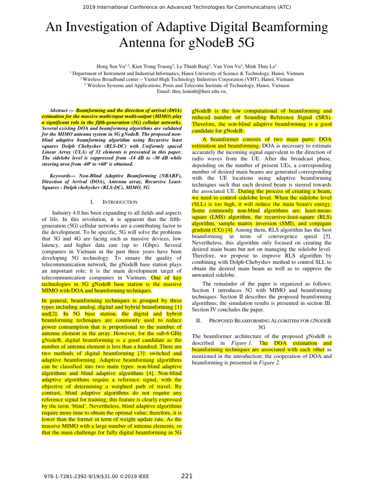
2019 International Conference on Advanced Technologies for Communications (ATC) An Investigation of Adaptive Digital Beamforming Antenna for gNodeB 5G 1 Hong Son Vu1,2, Kien Trung Truong3, Le Thanh Bang2, Van Yem Vu1, Minh Thuy Le1 Department of Instrument and Industrial Informatics, Hanoi University of Science & Technology, Hanoi, Vietnam 2 Wireless Broadband center – Viettel High Technology Industries Corporation (VHT), Hanoi, Vietnam 3 Wireless Systems and Applications, Posts and Telecoms Institute of Technology, Hanoi, Vietnam Email: thuy.leminh@hust.edu.vn, Abstract — Beamforming and the direction of arrival (DOA) estimation for the massive multi-input multi-output (MIMO) play a significant role in the fifth-generation (5G) cellular networks. Several existing DOA and beamforming algorithms are validated for the MIMO antenna system in 5G gNodeB. The proposed nonblind adaptive beamforming algorithm using Recursive least squares Dolph Chebyshev (RLS-DC) with Uniformly spaced Linear Array (ULA) of 32 elements is presented in this paper. The sidelobe level is suppressed from -14 dB to -30 dB while steering area from -60o to +60o is obtained. Keywords— Non-Blind Adaptive Beamforming (NBABF), Direction of Arrival (DOA), Antenna array, Recursive LeastSquares - Dolph chebyshev (RLS-DC), MIMO, 5G I. INTRODUCTION Industry 4.0 has been expanding to all fields and aspects of life. In this revolution, it is apparent that the fifthgeneration (5G) cellular networks are a contributing factor to the development. To be specific, 5G will solve the problems that 3G and 4G are facing such as massive devices, low latency, and higher data rate (up to 1Gbps). Several companies in Vietnam in the past three years have been developing 5G technology. To ensure the quality of telecommunication network, the gNodeB base station plays an important role; it is the main development target of telecommunication companies in Vietnam. One of key technologies in 5G gNodeB base station is the massive MIMO with DOA and beamforming techniques. In general, beamforming techniques is grouped by three types including analog, digital and hybrid beamforming [1] and[2]. In 5G base station, the digital and hybrid beamforming techniques are commonly used to reduce power consumption that is proportional to the number of antenna element in the array. However, for the sub-6 GHz gNodeB, digital beamforming is a good candidate as the number of antenna element is less than a hundred. There are two methods of digital beamforming [3]: switched and adaptive beamforming. Adaptive beamforming algorithms can be classified into two main types: non-blind adaptive algorithms and blind adaptive algorithms [4]. Non-blind adaptive algorithms require a reference signal, with the objective of determining a weighted path of travel. By contrast, blind adaptive algorithms do not require any reference signal for training; this feature is clearly expressed by the term ‘blind’. Nevertheless, blind adaptive algorithms require more time to obtain the optimal value; therefore, it is lower than the former in term of weight update rate. As the massive MIMO with a large number of antenna elements, so that the main challenge for fully digital beamforming in 5G 978-1-7281-2392-9/19/$31.00 ©2019 IEEE gNodeB is the low computational of beamforming and reduced number of Sounding Reference Signal (SRS). Therefore, the non-blind adaptive beamforming is a good candidate for gNodeB. A beamformer consists of two main parts: DOA estimation and beamforming. DOA is necessary to estimate accurately the incoming signal equivalent to the direction of radio waves from the UE. After the broadcast phase, depending on the number of present UEs, a corresponding number of desired main beams are generated corresponding with the UE locations using adaptive beamforming techniques such that each desired beam is steered towards the associated UE. During the process of creating a beam, we need to control sidelobe level. When the sidelobe level (SLL) is too high, it will reduce the main beam's energy. Some commonly non-blind algorithms are: least-meansquare (LMS) algorithm, the recursive-least-square (RLS) algorithm, sample matrix inversion (SMI), and conjugate gradient (CG) [4]. Among them, RLS algorithm has the best beamforming in term of convergence speed [5]. Nevertheless, this algorithm only focused on creating the desired main beam but not on managing the sidelobe level. Therefore, we propose to improve RLS algorithm by combining with Dolph-Chebyshev method to control SLL to obtain the desired main beam as well as to suppress the unwanted sidelobe. The remainder of the paper is organized as follows: Section I introduces 5G with MIMO and beamforming techniques. Section II describes the proposed beamforming algorithms; the simulation results is presented in section III. Section IV concludes the paper. II. PROPOSED BEAMFORMING ALGORITHM FOR GNODEB 5G The beamformer architecture of the proposed gNodeB is described in Figure 1. The DOA estimation and beamforming techniques are associated with each other as mentioned in the introduction; the cooperation of DOA and beamforming is presented in Figure 2. 221 2019 International Conference on Advanced Technologies for Communications (ATC) Figure 4. Geometry of ULAs of 2K elements Figure 1. Block diagram of digital beamformer in 5G base station If a incident wave is coming to the array at the θ angle , the wave font arrives at k + 1 element sooner than at k element; the differential distance along the two ray paths is dsinθ. The array factor is defined as: K AF(θ ) = ∑ We − jn 2 Π d sin θ λ n n =− K Figure 2. Block diagram of DOA and adaptive beamforming cooperation The flowchart of designing the proposed beamformer is described as follows: K = ∑ae − n 2 Π d sin θ j +δ n λ (1) n n =− K where Wn = an e jδ n is the complex weight corresponding to the excitation of the element nth. Structure of a non-blind adaptive beamforming is presented in Figure 5. For 5G base station, reference signal can be Sounding Reference Signal which is sent from UE in uplink. This signal creation is presented in [7] and gives the θ angle. The weight vectors are then determined based on SRS using suitable non-blind beamforming algorithms Figure 5. A diagram of a non-blind adaptive beamforming We will start first with the principle of RLS. The RLS adaptive algorithm directly approximates the Wiener solution using the least mean squares method to adjust the weight vectors without placing additional burden approximately an optimization process [8]. In the least mean squares method, weight vectors are chosen to minimize the objective function J w ,w* [9]. The objective function of the RLS method can be rewritten as follows: k J w ,w* = ∑ µ k −1 e(i ) 2 (2) i =1 Figure 3. Flowchart of designing the proposed beamformer In this study, the MIMO antenna array is a Uniformly spaced Linear Array (ULA) consisting of 32 elements [6] as shown in Figure 4. 978-1-7281-2392-9/19/$31.00 ©2019 IEEE where e(i) is error signal, 0 < µ < 1 is forgetting factor, and μ is selected close to 1. However, in a stationary environment, μ is equal to 1 since all data in the past and present must have equal weight [10]. Take the differential of objective function 222 J w ,w* according to w * and find its minimum. 2019 International Conference on Advanced Technologies for Communications (ATC) k k k −1 H k −1 * ∑ µ x(i) x (i) w(k ) = ∑ µ x(i )d (i ) i = 1 i = 1 In order to improve and manage sidelobes level, this study combined the RLS algorithm with the Dolph-Chebyshev sidelobe level method. The Dolph-Chebyshev method allows from the requirement of the sidelobe level to calculate the source amplitude that excites the elements. The idea of this method is to take the array coefficient into the form of the Chebyshev polynomial. At that time, the array factor has only one main maximum and the extra peaks will be smaller than the maximum, exactly in accordance with the requirement for the extra radiation level. Half-power beam width of antenna array when equal excitation and phase source excitation is calculated in [11]. (3) Set k R (k ) = ∑ µ k −1 x(i ) x H (i ) (4) i =1 And k P(k ) = ∑ µ k −1 x(i )d * (i ) (5) i =1 The expression is obtained w( k ) = R −1 ( k ) P ( k ) Π 1.391λ HPBW (Uniform) ≈ 2 − cos −1 Π Kd 2 (6) Recursive implementation in (4) and (5) is obtained. R (k ) = µ R( k − 1) + x (k ) x H (k ) * P (k ) = µ P( k − 1) + x (k )d (k ) (8) Weight of array when applying Dolph-Chebyshev [11]: (7) HPBW ( Dolph − Chebyshev ) = f ⋅ HPBW (Uniform) It is possible to obtain the inverse matrix R −1 (k ) using recursion according to R −1 ( k − 1) by using the lemma inverse matrix [5], thus avoiding direct inversion R ( k ) at each kth iteration. 2 f = 1 + 0.636 cosh (cosh −1 R0 ) 2 − Π 2 R 0 2 (9) R where R0 = 10 20 with R (dB) desired sidelobe level. Then weights generated by the RLS algorithm are multiplied by the weights generated by Dolph-Chebyshev. The simulation results of RLS-DC algorithm are obtained as in Section III. III. SIMULATION RESULTS A. Simulation Scenario Given initial conditions in these simulations were chosen regarding to the 3GPP requirements for the angular resolution up to 5° for UE moving speed up to 0.5 m/s in 5G wireless communications. With the estimated DOA by the Root-MUSIC algorithm, this study simulates beamforming algorithms with conditions: The array size is held to 32 elements, the number of samples is 1000 samples as the values of SNR are varied from 10-50dB and is illustrated in Figure 5. Holding SNR at 20dB and varying the number of samples from 100 to 10000 samples, snapshots = 50. The simulation frequency is 3.75GHz equivalent to the central frequency of licensed 5G gnodeB station in Vietnam. Simulation uses matlab program. And, this study ignores mutual coupling effect between elements. Figure 7. Assumption of the UE positioning for beamforming simulations Figure 6. Flow chart of RLS-DC algorithm 978-1-7281-2392-9/19/$31.00 ©2019 IEEE 223 2019 International Conference on Advanced Technologies for Communications (ATC) B. Simulation Results The simulation results are illustrated in Figure 7. It can be seen that the RLS algorithm for the main beam direction are right to the incoming signal direction of 00, eliminating the direction of noise to -350. The first sidelobe beam is reduced from - 14 dB with RLS to – 30 dB using RLS-DC. In addition, when using RLS-DC algorithms, sidelobe level were completely controlled under the expected value, - 30 dB in this case. Figure 10. Four beams are generated by RLS-DC algorithm (theta= -600, -300, 300 and 600) IV. CONCLUSTION In this paper, we proposed the non-blind adaptive beamforming algorithms RLS-DC. The sidelobe level is suppressed to 16 dB (from -14 dB to -30 dB) when applying RLS-DC. The steering area from -600 to 600 is obtained with low sidelobe level. The angular resolution is less than 5o for UE moving speed up to 0.5 m/s to meet the 3GPP requirement. RLS-DC is more suitable for embedded computer implementation due to its fast convergence rate. Figure 8. Array factor of ULA of 32 elements with RLS and RLS-DC algorithm (SNR=20dB, 1000 samples, R=30dB) In order to be able to compare the convergence rates of the RLS-DC algorithm, this study simulated the objective function after 50 iterations when the SNR are varied from 10 to 50 dB. The results are presented in Figure 8. It is realized that the ratio of signal to noise increases; the ability of convergence of algorithm is also smoother and at higher level. Figure 9. Objective function of RLS-DC after 50 iteration In the case of four connected UEs at four direction, 4 beamformers corresponding to 4 desired beams are generated towards the theta = -600, -300, 300 and 600 results as in the following figure. We can easily realize that the angle of the best sidelobe level is between -600 and 600. 978-1-7281-2392-9/19/$31.00 ©2019 IEEE REFERENCES [1] T. E. Bogale and L. B. Le, “Beamforming for multiuser massive MIMO systems: Digital versus hybrid analog-digital,” in 2014 IEEE Global Communications Conference, Austin, TX, USA, 2014, pp. 4066–4071. [2] S. Hur, T. Kim, D. J. Love, J. V. Krogmeier, T. A. Thomas, and A. Ghosh, “Millimeter Wave Beamforming for Wireless Backhaul and Access in Small Cell Networks,” IEEE Trans. Commun., vol. 61, no. 10, pp. 4391–4403, Oct. 2013. [3] A. Konstantinos and N. John, “Beamforming in 3G and 4G Mobile Communications: The Switched-Beam Approach,” in Recent Developments in Mobile Communications - A Multidisciplinary Approach, J. P. Macas, Ed. InTech, 2011. [4] E. Ali, M. Ismail, R. Nordin, and N. F. Abdulah, “Beamforming techniques for massive MIMO systems in 5G: overview, classification, and trends for future research,” Front. Inf. Technol. Electron. Eng., vol. 18, no. 6, pp. 753–772, Jun. 2017. [5] P. S. R. Diniz, Adaptive filtering: algorithms and practical implementation, 4th ed. New York: Springer, 2013. [6] T. D. Bui, Q. C. Nguyen, and M. T. Le, “Novel wideband circularly polarized antenna for wireless applications,” in 2017 IEEE Asia Pacific Microwave Conference (APMC), Kuala Lumpar, 2017, pp. 430–433. [7] E. Dahlman, S. Parkvall, and J. Sköld, 5G NR: the next generation wireless access technology. London San Diego, CA Cambridge, MA Oxford: Elsevier, Academic Press, 2018. [8] B. D. Van Veen and K. M. Buckley, “Beamforming: a versatile approach to spatial filtering,” IEEE ASSP Mag., vol. 5, no. 2, pp. 4– 24, Apr. 1988. [9] S. Werner, “Reduced complexity adaptive filtering algorithms with applications to communications systems,” Helsinki University of Technology, Helsinki, Finland, 2002. [10] Zhigang Rong, “Simulation of Adaptive Array Algorithms for CDMA Systems,” Virginia Polytechnic Institute and State University, Blacksburg, Virginia, 1996. [11] C. A. Balanis, Antenna theory: analysis and design, Fourth edition. Hoboken, New Jersey: Wiley, 2016. 224
