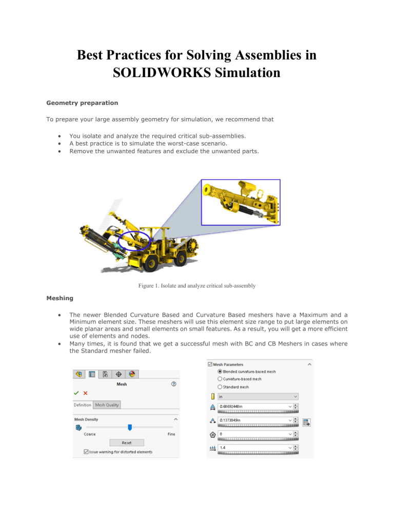
Best Practices for Solving Assemblies in SOLIDWORKS Simulation Geometry preparation To prepare your large assembly geometry for simulation, we recommend that • • • You isolate and analyze the required critical sub-assemblies. A best practice is to simulate the worst-case scenario. Remove the unwanted features and exclude the unwanted parts. Figure 1. Isolate and analyze critical sub-assembly Meshing • • The newer Blended Curvature Based and Curvature Based meshers have a Maximum and a Minimum element size. These meshers will use this element size range to put large elements on wide planar areas and small elements on small features. As a result, you will get a more efficient use of elements and nodes. Many times, it is found that we get a successful mesh with BC and CB Meshers in cases where the Standard mesher failed. Interferences • Check whether your assembly is having the interferences are not, if available remove them by applying proper mates or changing the dimensions(if possible). • Interferences are present in critical areas, and you want to resolve them by applying a Boolean operation. The tool to use is the Cavity tool under Insert>Mold. To remove the interference, edit the part you want to cut within the assembly, then select the Cavity tool, choose the part you want to use as cutting tool and the other as part to be cut. Gaps • Gaps can be seen in the same light as interferences. In the case of gaps, they don’t cause the mesher to fail, but the solver is unable to complete. This is because the presence of gaps in your assemblies can lead to structural instabilities. • The first challenge is to find any gaps, because often it is difficult to ‘see’ the presence of gaps in your model. • Handling gaps is much easier in 2021 because SOLIDWORKS Simulation has introduced 3 new parameters to help you overcome gaps in your models: Best Practices for Solving Large Assemblies in SOLIDWORKS Simulation video link for your reference by SOLIDWORKS: https://youtu.be/PF1pbwCs1Bc


