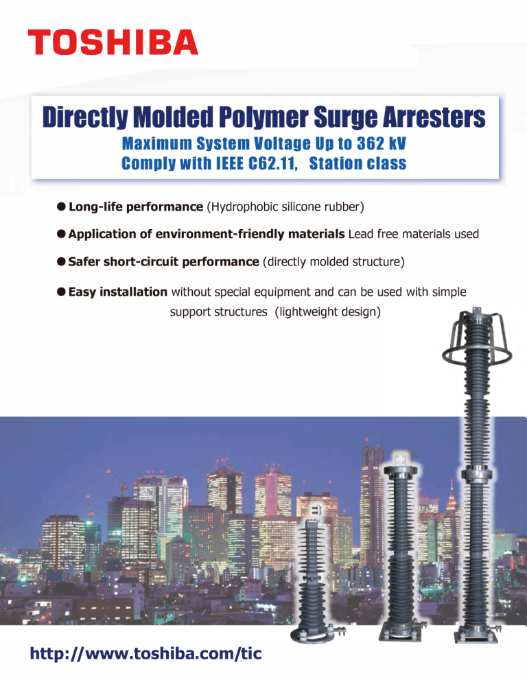
Directlv Molded Polvmer surue Arresters Maximum svstem Voltage Up to 362 kV Complv with IEEE C62.11, Station class • Long-life performance (Hydrophobic silicone rubber) • Application of environment-friendly materials Lead free materials used • Safer short-circuit performance (directly molded structure) • Easy installation without special equipment and can be used with simple support structures (lightweight design) http://www.toshiba.com/tic レターサイズ ̲215.9mm×279.4mm 1. Features of Toshiba polymer surge arresters Long-life performance Toshiba polymer surge arresters continue to show optimum performances even under extreme environmental conditions with heavy pollution, or in industrial, coastal or desert areas thanks to the use of silicone rubber which remains hydrophobic throughout its life cycle. These long life cycle performances have been fully verified by detailed evaluations such as pollution tests, boiling tests, long-term life performance tests in a coastal area, and other tests. Hydrophobicity of silicone rubber Applied ZnO elements Long-term life performance tests Compact and light weight design Toshiba polymer surge arresters can be reduced in size and weight by applying ZnO elements with high energy absorption capability and the silicone directly mold design. Toshiba’ s surge arresters do not require special heavy equipment thanks to their compact and light weight design, making installation easier. In some case, installation of surge arresters on a very simple support structure or an additional structure can be available. Example of simple support structure Utilization of support structure of adjacent equipment Highly safe short-circuit performance Toshiba’ s polymer surge arresters have a structure in which an internal section with stacked ZnO elements is directly molded by silicone rubber. Because there is no gas space in the arresters and thanks to the suitable design of the internal section, pressure can successfully relief by splitting the silicone rubber, thus preventing the internal parts from bouncing out in emergency case of a short-circuit caused by a surge arrester failure . View of short circuit test Manufacturing certified by ISO9001, ISO14001 under strict quality control 2 レターサイズ ̲215.9mm×279.4mm 2. Performance Toshiba’ s directly molded polymer surge arresters, which are the gapless ZnO element type, comply with IEEE standard C62.11-2012. These surge arresters cover the system voltages up to 362kV as summarized in Fig. 1. The principal characteristics of each type of surge arrester are summarized in Table 1. Max. system voltage (kV) 362 245 170 145 123 72.5 Less than 72.5 Classification Station Station Station Station Arrester type RVLQC-nnPLHY RVLQD-nnHPLHY RVLQC-nnHPLHY RVLQB-nnHPLHY Notes 1) Various surge arresters outside of this range are possible according to the customer’ s needs. 2) “nn” in Arrester type denotes duty-cycle voltage. Fig. 1 Covered range (system voltages) Table 1 Standard ratings Arrester type RVLQC-nnPLHY RVLQD-nnHPLHY RVLQC-nnHPLHY RVLQB-nnHPLHY Max. system voltage (Um) [kVrms] < 72.5 kV 170 245 362 Duty-cycle voltage [kVrms] 3 ~48 54 ~150 168 ~228 258 ~288 Station Station Station Station Classification Lightning impulse classification current [kAcrest] 10 10 10 10 High current impulse capability [kAcrest] 100 100 100 100 High current [kArms] 50 50 65 65 Low current [Arms] 600 600 600 600 [kJ/kV_MCOV] 7.5 7.5 7.5 15 [inch-lbs (Nm)] 7080 (800) 8850 (1000) 20350 (2300) 26550 (3000) Pressure relief capability Energy rating Max. design cantilever load Notes 1) Surge arresters with larger energy absorption capability are available. 2) The energy rating means the dissipated total energy per two shots of switching surge impulses that the surge arrester can withstand without losing thermal stability. 3 レターサイズ ̲215.9mm×279.4mm 3. Detailed characteristics (1) Max. system voltage; up to 52kV Station class : RVLQC-nnPLHY Catalog number RVLQC-3PLHY RVLQC-6PLHY RVLQC-9PLHY RVLQC-10PLHY RVLQC-12PLHY RVLQC-15PLHY RVLQC-18PLHY RVLQC-21PLHY RVLQC-24PLHY RVLQC-27PLHY RVLQC-30PLHY RVLQC-33PLHY RVLQC-36PLVY RVLQC-39PLHY RVLQC-42PLHY RVLQC-45PLHY RVLQC-48PLHY Maximum discharge voltage Dutycycle voltage MCOV kVrms 3 6 9 10 12 15 18 21 24 27 30 33 36 39 42 45 48 kVrms 2.55 5.1 7.65 8.4 10.2 12.7 15.3 17.0 19.5 22.0 24.4 26.7 29.0 31.5 34.0 36.4 39.0 Lightning current imp. 8/20 μs 5 kA kVp 8.4 13.8 22.2 25.2 27.6 36.0 41.4 49.8 55.2 63.6 69.0 77.4 82.8 91.2 96.6 105 111 10 kA kVp 8.9 14.5 23.4 26.6 29.0 37.9 43.5 52.4 58.0 66.9 72.5 81.4 87.0 95.9 102 111 116 20 kA kVp 9.8 16.0 25.8 29.4 32.0 41.8 48.0 57.8 64.0 73.8 80.0 89.8 96.0 106.0 112 122 128 Switching surge currenrt imp. 40 kA 0.5 kA kVp kVp 11.0 7.1 18.0 11.7 29.0 18.9 33.0 21.4 36.0 23.4 47.0 30.6 54.0 35.1 65.0 42.3 72.0 46.8 83.0 54.0 90.0 58.5 101.0 65.7 108.0 70.2 119.0 77.4 126 81.9 137 89.1 144 93.6 1 kA kVp 7.3 12.0 19.4 22.0 24.0 31.4 36.0 43.4 48.0 55.4 60.0 67.4 72.0 79.4 84 91.4 96 2 kA kVp 7.7 12.6 20.3 23.0 25.2 32.9 37.8 45.5 50.4 58.1 63.0 70.7 75.6 83.3 88.2 95.9 101 10 kA kVp 9.9 16.2 26.1 29.7 32.4 42.3 48.6 58.5 64.8 74.7 81.0 90.9 97.2 108 114 124 130 Dimension Mass Outline 1 2 Dimension, Mass and Outline No. Duty-cycle voltage (kV) Height inches (mm) Creepage distance inches (mm) Grading ring diameter inches (mm) Mass lbs (kg) Outline Figure 1 3 to 36 19.1 (484) 51.2 (1300) NA 33.0 (15) A 2 39 to 48 33.0 (862) 102 (2600) NA 46.2 (21) B Line terminal (NEMA Type) Ground terminal A Insulating base 4 B Outline Figure レターサイズ ̲215.9mm×279.4mm 3. Detailed characteristics (2) Max. system voltage; up to 170kV Station class : RVLQD-nnHPLHY Catalog number RVLQD-54HPLHY RVLQD-60HPLHY RVLQD-66HPLHY RVLQD-69HPLHY RVLQD-72HPLHY RVLQD-75HPLHY RVLQD-84HPLHY RVLQD-90HPLHY RVLQD-96HPLHY RVLQD-102HPLHY RVLQD-108HPLHY RVLQD-120HPLHY RVLQD-126HPLHY RVLQD-132HPLHY RVLQD-138HPLHY RVLQD-144HPLHY RVLQD-150HPLHY Maximum discharge voltage Dutycycle voltage MCOV kVrms kVrms 54 60 66 69 72 75 84 90 96 102 108 120 126 132 138 144 150 43.7 48.6 53.4 55.8 58.3 60.7 68.0 72.9 77.7 82.6 87.4 97.2 102 106 111 116 121 Switching surge currenrt imp. Lightning current imp. 8/20 μs 5 kA kVp 129 138 156 165 165 174 193 211 220 238 247 275 293 302 321 330 348 10 kA kVp 138 147 167 177 177 187 206 226 236 255 265 294 314 324 343 353 373 20 kA kVp 153 164 186 197 197 208 230 252 263 284 295 328 350 361 383 394 415 40 kA kVp 174 187 211 224 224 236 261 286 298 323 336 373 398 410 435 447 472 0.5 kA kVp 110 118 133 141 141 149 164 180 188 203 211 235 250 258 274 281 297 1 kA kVp 113 121 137 145 145 153 169 185 193 209 217 241 257 265 281 289 305 2 kA kVp 117 125 142 150 150 159 175 192 200 217 225 250 267 275 292 300 317 Steep Dimension curr. imp. Mass Outline 10 kA kVp 148 159 180 190 190 201 222 243 253 275 285 317 338 348 369 372 401 1 2 3 4 Dimension, Mass and Outline Height inches (mm) Creepage distance inches (mm) Grading ring diameter inches (mm) Mass lbs (kg) Outline Figure 1 Duty-cycle voltage (kV) 54 to 84 41.2 (1045) 98.4 (2500) NA 55.1 (25) A 2 90 to 108 49.1 (1245) 126 (3200) NA 59.5 (27) A 3 120 to 132 56.9 (1445) 152 (3850) NA 66.1 (30) A 4 138 to 150 64.8 (1645) 177 (4500) NA 77.1 (35) A No. A Line terminal (NEMA Type) Insulating base & Ground terminal Outline Figure 5 レターサイズ ̲215.9mm×279.4mm 3. Detailed characteristics (3) Max. system voltage; up to 245kV Station class : RVLQC-nnHPLHY Catalog number RVLQC-168HPLHY RVLQC-172HPLHY RVLQC-174HPLHY RVLQC-180HPLHY RVLQC-192HPLHY RVLQC-196HPLHY RVLQC-198HPLHY RVLQC-210HPLHY RVLQC-216HPLHY RVLQC-228HPLHY Maximum discharge voltage Dutycycle voltage MCOV Lightning current imp. 8/20 μs kVrms 168 172 174 180 192 196 198 210 216 228 kVrms 131 140 140 144 152 158 160 170 174 184 5 kA kVp 387 401 401 414 442 456 456 483 497 525 10 kA kVp 406 421 421 435 464 479 479 508 522 551 20 kA kVp 448 464 464 480 512 528 528 560 576 608 40 kA kVp 504 522 522 540 576 594 594 630 648 684 Switching surge currenrt imp. 0.5 kA kVp 328 340 340 351 375 387 387 410 422 445 1 kA kVp 336 348 348 360 384 396 396 420 432 456 2 kA kVp 353 366 366 378 404 416 416 441 454 479 Steep Dimension curr. imp. Mass Outline 10 kA kVp 454 470 470 486 519 535 535 567 584 616 1 2 Dimension, Mass and Outline No. Duty-cycle voltage (kV) Height inches (mm) Creepage distance inches (mm) Grading ring diameter inches (mm) Mass lbs (kg) Outline Figure 1 168 to 216 80.9 (2055) 236 (6000) 23.6 (600) 144 (65) A 2 228 96.7 (2455) 299 (7600) 23.6 (600) 166 (75) A Line terminal (NEMA Type) Ground terminal A Insulating base 6 Outline Figure レターサイズ ̲215.9mm×279.4mm 5. Detailed characteristics (4) Max. system voltage; up to 362kV Station class : RVLQB-nnHPLHY Catalog number RVLQB-264HPLHY RVLQB-276HPLHY RVLQB-288HPLHY Maximum discharge voltage Dutycycle voltage MCOV kVrms 264 276 288 kVrms 212 220 230 Switching surge currenrt imp. Lightning current imp. 8/20 μs 5 kA kVp 574 598 623 10 kA kVp 607 633 658 20 kA kVp 668 696 725 40 kA kVp 747 779 810 0.5 kA kVp 478 499 519 1 kA kVp 494 515 536 2 kA kVp 517 539 561 Steep Dimension Mass curr. imp. Outline 10 kA kVp 663 691 1 720 Dimension, Mass and Outline No. 1 Duty-cycle voltage (kV) 264 to 288 Height inches (mm) Creepage distance inches (mm) Grading ring diameter inches (mm) Mass lbs (kg) Outline Figure 112 (2855) 370 (9400) 23.6 (600) 287 (130) A Line terminal (NEMA Type) Ground terminal A Insulating base Outline Figure Notes 1) Surge arresters with other rated voltage are available according to the customer’s needs. 2) Surge arresters with other specifications are available according to the customer’s needs. 3) The wave shapes of switching surge and steep current impulse are as follows. - Switching surge current impulse: virtual front time greater than 45 µs but less than 60 µs - Steep current impulse: virtual front time of 1 µs. 4) Other types of line and grounding terminal are available according to the customer’s needs 7 レターサイズ ̲215.9mm×279.4mm TOSHIBA INTERNATIONAL CORPORATION INDUSTRIAL DIVISION TRANSMISSION & DISTRIBUTION DIVISION 13131 West Little York Road, Houston, Texas 77041, USA Phone: (800)231-1412 or 713-466-0277 Fax: 713-896-5242 E-mail: TD@tic.toshiba.com TOSHIBA CORPORATION Social Infrastructure SYSTEMS COMPANY 72-34, Horikawa-cho, Saiwai-Ku, Kawasaki 212-8585, Japan Phone: +81-44-331-1473 Fax: +81-44-548-9541 ・The information contained herein is as of September, 2015. ・The information contained herein is subject to change without notice. ・The information contained herein is presented only as a guide for the applications of our products. No responsibility is assumed by TOSHIBA for any infringements of patents or other rights of the third parties which may result from its use. No license is granted by implication or otherwise under any patent or patent rights of TOSHIBA or others. ・TOSHIBA products should not be embedded to the downstream products which are prohibited to be produced and sold, under any law. ・TOSHIBA does not take any responsibility for incidental damage (including loss of business profit, business interruption, loss of business information, and other pecuniary damage) arising out of the use or disability to use TOSHIBA products. ・TOSHIBA products described in this document may include products subject to the foreign exchange and foreign trade laws. ・TOSHIBA products described in this document may contain components made in the United States and subject to export control of the U.S. authorities. Diversion contrary to the U.S. law is prohibited. 4 http://www.toshiba.com/tic 5613-3 1511G1
