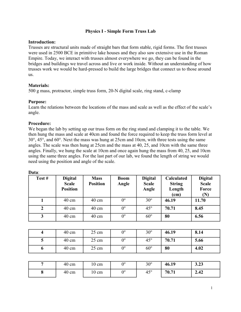
Physics I - Simple Form Truss Lab Introduction: Trusses are structural units made of straight bars that form stable, rigid forms. The first trusses were used in 2500 BCE in primitive lake houses and they also saw extensive use in the Roman Empire. Today, we interact with trusses almost everywhere we go, they can be found in the bridges and buildings we travel across and live or work inside. Without an understanding of how trusses work we would be hard-pressed to build the large bridges that connect us to those around us. Materials: 500 g mass, protractor, simple truss form, 20-N digital scale, ring stand, c-clamp Purpose: Learn the relations between the locations of the mass and scale as well as the effect of the scale’s angle. Procedure: We began the lab by setting up our truss form on the ring stand and clamping it to the table. We then hung the mass and scale at 40cm and found the force required to keep the truss form level at 30°, 45°, and 60°. Next the mass was hung at 25cm and 10cm, with three tests using the same angles. The scale was then hung at 25cm and the mass at 40, 25, and 10cm with the same three angles. Finally, we hung the scale at 10cm and once again hung the mass from 40, 25, and 10cm using the same three angles. For the last part of our lab, we found the length of string we would need using the position and angle of the scale. Data: Test # Digital Scale Position Mass Position Boom Angle Digital Scale Angle 30o Calculated String Length (cm) 46.19 Digital Scale Force (N) 11.70 1 40 cm 40 cm 0o 2 40 cm 40 cm 0o 45o 70.71 8.45 3 40 cm 40 cm 0o 60o 80 6.56 4 40 cm 25 cm 0o 30o 46.19 8.14 5 40 cm 25 cm 0o 45o 70.71 5.66 6 40 cm 25 cm 0o 60o 80 4.02 7 40 cm 10 cm 0o 30o 46.19 3.23 8 40 cm 10 cm 0o 45o 70.71 2.42 1 9 40 cm 10 cm 0o 60o 80 1.90 10 25 cm 40 cm 0o 30o 28.87 18.09 40 cm o o 35.36 13.05 o 11 25 cm 0 o 45 12 25 cm 40 cm 0 60 50 10.01 13 25 cm 25 cm 0o 30o 28.87 11.42 14 25 cm 25 cm 0o 45o 35.36 7.84 15 25 cm 25 cm 0o 60o 50 6.81 Test # Digital Scale Position Mass Position Boom Angle Digital Scale Angle 16 25 cm 10 cm 0o 30o Calculated String Length (cm) 28.87 Digital Scale Force (N) 5.27 17 25 cm 10 cm 0o 45o 35.36 3.63 18 25 cm 10 cm 0o 60o 50 2.99 19 10 cm 40 cm 0o 30o 11.55 >20 20 10 cm 40 cm 0o 45o 14.14 >20 21 10 cm 40 cm 0o 60o 20 >20 22 10 cm 25 cm 0o 30o 11.55 >20 23 10 cm 25 cm 0o 45o 14.14 17.62 24 10 cm 25 cm 0o 60o 20 14.75 25 10 cm 10 cm 0o 30o 11.55 9.23 26 10 cm 10 cm 0o 45o 14.14 7.19 27 10 cm 10 cm 0o 60o 20 6.39 2 Questions: 1) Which boom setup completed the objectives in the best possible manner (sign is farthest from wall without breaking the cable and uses the smallest amount of cable)? Test Number 6 2) In order to provide the strongest support, where is the best place to hang the mass in relation to the scale attachment? The locations for test number 9. The mass at 10cm and the scale at 40 cm. 3) What is the relationship between the angle of the scale and the tension in the string? They are inversely proportional, the greater the angle the lower the force (up to 90°). 4) Compare the force measurements for when the scale and mass are attached at the same position (trials 1-3, 13-15, & 25-27)? When the mass and the scale are at the same position the forces for any given angle will be the same. 5) Which boom below would produce the most tension in the string? Why? Assume the mass in each figure is the same. Boom c. would create the greatest tension in the string. This is because the mass and scale are hung at the same locations in each so the distance does not matter just the angle. Conclusion: In this lab I learned that the smaller the angle the greater the force required to balance the truss. This is because the closer the angle is to parallel the greater the horizontal component of the force and the smaller the vertical component. During our testing we most likely did not have the truss perfectly level or the scale at the exact angle we were testing which could cause our force values to be greater of smaller than they should have been. References: Lab handout, Google 3


