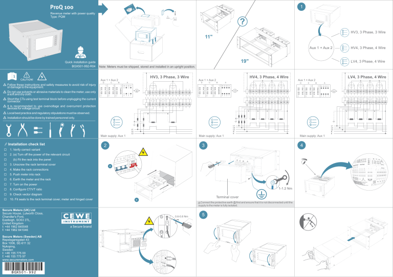
) QM meter 0 (Pr quality Q 10d powe Provenue an ProQ 100 1 Re ick Qu ide n gu 01 atio 2-R tall -99 ins 01 X5 BG Revenue meter with power quality Type: PQM ? HV3, 3 Phase, 3 Wire 11" Aux 1 + Aux 2 Quick installation guide BGX501-992-R04 19" D Do not use solvents or abrasive materials to clean the meter, use only a soft and dry cloth. LV4, 3 Phase, 4 Wire Note: Meters must be shipped, stored and installed in an upright position. HV3, 3 Phase, 3 Wire Aux 1 + Aux 2 Follow these instructions and safety measures to avoid risk of injury or damage to the equipment. C B HV4, 3 Phase, 4 Wire Aux 1 + Aux 2 A D C B A 04 03 02 01 5 6 7 8 9 0 1 2 3 4 5 6 7 8 9 0 1 2 3 4 5 6 7 8 9 5 6 7 8 9 3 2 D C B A 04 03 02 01 0 1 2 3 4 4 LV4, 3 Phase, 4 Wire Aux 1 + Aux 2 0 1 2 3 4 1 5 6 7 8 9 0 1 2 3 4 5 6 7 8 9 04 03 02 01 0 1 2 3 4 5 6 7 8 9 4 3 2 0 1 2 3 4 1 5 6 7 8 9 0 1 2 3 4 5 6 7 8 9 0 1 2 3 4 4 3 Short the CTs using test terminal block before unplugging the current connector. It is recommended to use overvoltage and overcurrent protection devices for voltage circuit. Local best practice and regulatory stipulations must be observed. Installation should be done by trained personnel only. Main supply: Aux 1 Installation check list ¨ 1. Verify correct variant ¨ 2. (a) Turn off the power of the relevant circuit Main supply: Aux 1 (b) Fit the rack into the panel ¨ 3. Unscrew the rack terminal cover ¨ 4. Make the rack connections ¨ 5. Push meter into rack ¨ 6. Earth the meter and the rack ¨ 7. Turn on the power ¨ 8. Configure CT/VT ratio ¨ 9. Check vector diagram ¨ 10. Fit seals to the rack terminal cover, meter and hinged cover Main supply: Aux 1 4 3 2 ¨ D C B A a Terminal cover b Connect the protective earth first and ensure that it is not disconnected until the supply to the meter is fully isolated. Secure Meters (UK) Ltd Secure House, Lulworth Close, Chandler's Ford, Eastleigh, SO53 3TL, United Kingdom t: +44 1962 840048 f: +44 1962 841046 Secure Meters (Sweden) AB Repslagaregatan 43 Box 1006, SE-611 32 Nykoping, Sweden t: +46 155 775 00 f: +46 155 775 97 www.securemeters.com BGX5 0 1 - 9 9 2 0.6-0.8 Nm a Secure brand HV4, 3 Phase, 4 Wire 5 2 1 6 Hinge cover 6 1 2 3 4 5 7 8 9 5-10 cm 7 8 1 2 3 4 5 6 7&8 9 Home Up Enter Down Back L1 Calibration LED 1 (Active energy) Alarm/Pulse output LEDs L2 Calibration LED 2 (Reactive/Apparent energy) 9 D C B ProQ100 Voltage Energy Current ON Configurable button 10 30-10-17 Quality Power Events Power factor Setup Vector 0.6-0.8 Nm b ON ON ProQ100 Real CTR VTR ? 100 A/1 A ? 11 kV/110 V c ConfigView 16:45 30-10-17 Current Energy Power Quality Power factor Events Vector Setup System d Note: Make sure that the LAN cable is working and is properly connected. Refer to the user manual for configuration related details. SFP connector (fibre/copper) CT VT 1000 Mbit/s Online monitoring/third party integration 0.5 Nm 10/100 Mbit/s 9.6 kbit/s 9.6 kbit/s Communication with external modem 9.6/57.6 kbit/s M3 x 12 mm Environmental and safety specifications Operating range -20°C to +60°C Temperature -40°C to +70°C Storage range Operating humidity up to 95% non-condensing Altitude level up to 2000 m Pollution degree 2 CATIII (rated voltage 300 V for measuring circuits and Overvoltage category auxiliary inputs ) Use Rack-mounted, indoor use only Protective class I Ingress protection IP54 (front), IP20 (rear) Mechanical specifications For CT, VT and Aux.: Copper, 2.5 mm2 For pulse input/output: Copper, 1.5 mm2 For voltage, current and protective earth terminals: Recommended PVC multi strand, voltage grade up to 1100 V, current rating up to 20 A (rated up to 105°C) cable For Aux. and pulse I/O terminals: PVC multi strand, voltage grade up to 1100 V, current rating up to 2.5 A (rated up to 105°C) Electrical specifications Connection type: Wiring Voltage range HV3/HV4/LV4 3P 4W | 3P 3W 3 x 57.7/100 to 240/415 V (3P 4W) 2 x 100 to 120 V (3P 3W) (-30% to +20%) Current range Ibasic: 1 to 5 A (configurable) Imax: up to 10 A (configurable) Aux. power supply (Aux. 1 and Aux. 2) 50-230 V AC/DC ± 20%, 50/60 Hz, 25 VA/15 W max. Frequency 50/60 Hz ± 5% Voltage circuit Rated impulse voltage STOC Pulse output Configurable pulse input/ Output SFP module If power drawn from Aux supply Current circuit <0.1 VA/phase (for Ibasic) Burden Optical port A a ON 16:43 Real USB port <0.5 VA/phase (for Vnominal) Aux. power supply 25 VA/15 W max If power drawn from VT (self powered) Voltage circuit < 5 W and 5 VA/phase (approx.) @ 63.5 V 4 kV 7 x Imax for 10 seconds, 10 x Imax for 3 seconds, 20 x Imax for 1 second 24-230 V AC/DC at max. continuous current 100 mA If configured as pulse output, 24-230 V AC/DC at max. continuous current 100 mA If configured as pulse input, 24-230 V DC or 40-230 V AC Pulse inputs are protected by clamping the input voltage to 300 V AC Voltage range: 3.3 V ± 5%, Max. load:600 mA Standards compliance Standards BS EN/IEC 62053-22, BS EN/IEC 62053-24, BS EN/IEC 6052-31, BS EN/IEC 61000-4-30 (class A), BS EN/IEC 62586-2, BS EN/IEC 60297, DIN 43862 Note: Refer to the user manual for more details. D C B A


