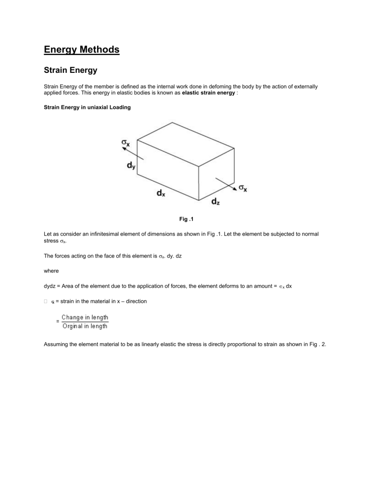
Energy Methods Strain Energy Strain Energy of the member is defined as the internal work done in defoming the body by the action of externally applied forces. This energy in elastic bodies is known as elastic strain energy : Strain Energy in uniaxial Loading Fig .1 Let as consider an infinitesimal element of dimensions as shown in Fig .1. Let the element be subjected to normal stress x. The forces acting on the face of this element is x. dy. dz where dydz = Area of the element due to the application of forces, the element deforms to an amount = x dx x = strain in the material in x – direction Assuming the element material to be as linearly elastic the stress is directly proportional to strain as shown in Fig . 2. Fig .2 From Fig .2 the force that acts on the element increases linearly from zero until it attains its full value. Hence average force on the element is equal to ½ x . dy. dz. Therefore the workdone by the above force Force = average force x deformed length = ½ x. dydz . x . dx For a perfectly elastic body the above work done is the internal strain energy “du”. where dv = dxdydz = Volume of the element By rearranging the above equation we can write The equation (4) represents the strain energy in elastic body per unit volume of the material its strain energy – density „uo' . From Hook's Law for elastic bodies, it may be recalled that In the case of a rod of uniform cross – section subjected at its ends an equal and opposite forces of magnitude P as shown in the Fig .3. Fig .3 Modulus of resilience : Fig .4 Suppose „ x„ in strain energy equation is put equal to y i.e. the stress at proportional limit or yield point. The resulting strain energy gives an index of the materials ability to store or absorb energy without permanent deformation So The quantity resulting from the above equation is called the Modulus of resilience The modulus of resilience is equal to the area under the straight line portion „OY' of the stress – strain diagram as shown in Fig .4 and represents the energy per unit volume that the material can absorb without yielding. Hence this is used to differentiate materials for applications where energy must be absorbed by members. Modulus of Toughness : Fig .5 Suppose „' [strain] in strain energy expression is replaced by R strain at rupture, the resulting strain energy density is called modulus of toughness From the stress – strain diagram, the area under the complete curve gives the measure of modules of toughness. It is the materials. Ability to absorb energy upto fracture. It is clear that the toughness of a material is related to its ductility as well as to its ultimate strength and that the capacity of a structure to withstand an impact Load depends upon the toughness of the material used. ILLUSTRATIVE PROBLEMS 1. Three round bars having the same length „L' but different shapes are shown in fig below. The first bar has a diameter „d' over its entire length, the second had this diameter over one – fourth of its length, and the third has this diameter over one eighth of its length. All three bars are subjected to the same load P. Compare the amounts of strain energy stored in the bars, assuming the linear elastic behavior. Solution : From the above results it may be observed that the strain energy decreases as the volume of the bar increases. 2. Suppose a rod AB must acquire an elastic strain energy of 13.6 N.m using E = 200 GPa. Determine the required yield strength of steel. If the factor of safety w.r.t. permanent deformation is equal to 5. Solution : Factor of safety = 5 Therefore, the strain energy of the rod should be u = 5 [13.6] = 68 N.m Strain Energy density The volume of the rod is Yield Strength : As we know that the modulus of resilience is equal to the strain energy density when maximum stress is equal to x . It is important to note that, since energy loads are not linearly related to the stress they produce, factor of safety associated with energy loads should be applied to the energy loads and not to the stresses. Strain Energy in Bending : Fig .6 Consider a beam AB subjected to a given loading as shown in figure. Let M = The value of bending Moment at a distance x from end A. From the simple bending theory, the normal stress due to bending alone is expressed as. ILLUSTRATIVE PROBLEMS 1. Determine the strain energy of a prismatic cantilever beam as shown in the figure by taking into account only the effect of the normal stresses. Solution : The bending moment at a distance x from end A is defined as Substituting the above value of M in the expression of strain energy we may write Problem 2 : a. b. Determine the expression for strain energy of the prismatic beam AB for the loading as shown in figure below. Take into account only the effect of normal stresses due to bending. Evaluate the strain energy for the following values of the beam P = 208 KN ; L = 3.6 m = 3600 mm A = 0.9 m = 90mm ; b = 2.7m = 2700 mm 8 E = 200 GPa ; I = 104 x 10 mm Solution: a. 4 Bending Moment : Using the free – body diagram of the entire beam, we may determine the values of reactions as follows: RA = Pb/ L RB = Pa / L For Portion AD of the beam, the bending moment is For Portion DB, the bending moment at a distance v from end B is Strain Energy : Since strain energy is a scalar quantity, we may add the strain energy of portion AD to that of DB to obtain the total strain energy of the beam. b. Substituting the values of P, a, b, E, I, and L in the expression above. Problem 3) Determine the modulus of resilience for each of the following materials. a. Stainless steel . E = 190 GPa y = 260MPa b. Malleable constantan E = 165GPa y = 230MPa c. Titanium E = 115GPa y = 830MPa d. Magnesium E = 45GPa y = 200MPa 4) For the given Loading arrangement on the rod ABC determine (a). The strain energy of the steel rod ABC when P = 40 KN. (b). The corresponding strain energy density in portions AB and BC of the rod. Complementary Strain Energy : Consider the stress strain diagram as shown Fig 39.1. The area enclosed by the inclined line and the vertical axis is called the complementary strain energy. For a linearly elastic materials the complementary strain energy and elastic strain energy are the same. Fig 39.1 Let us consider elastic non linear primatic bar subjected to an axial load. The resulting stress strain plot is as shown. Fig 39. 2 The new term complementary work is defined as follows So In geometric sense the work W* is the complement of the work „W' because it completes rectangle as shown in the above figure Complementary Energy Likewise the complementary energy density u* is obtained by considering a volume element subjected to the stress 1 and1, in a manner analogous to that used in defining the strain energy density. Thus The complementary energy density is equal to the area between the stress strain curve and the stress axis. The total complementary energy of the bar may be obtained from u* by integration Sometimes the complementary energy is also called the stress energy. Complementary Energy is expressed in terms of the load and that the strain energy is expressed in terms of the displacement. Castigliano's Theorem : Strain energy techniques are frequently used to analyze the deflection of beam and structures. Castigliano's theorem were developed by the Italian engineer Alberto castigliano in the year 1873, these theorems are applicable to any structure for which the force deformation relations are linear Castigliano's Therom : Consider a loaded beam as shown in figure Let the two Loads P1 and P2 produce deflections Y1 and Y2 respectively strain energy in the beam is equal to the work done by the forces. Let the Load P1 be increased by an amount P1. Let P1 and P2 be the corresponding changes in deflection due to change in load to P1. Now the increase in strain energy Suppose the increment in load is applied first followed by P1 and P2 then the resulting strain energy is Since the resultant strain energy is independent of order loading, Combing equation 1, 2 and 3. One can obtain or upon taking the limit as P1 approaches zero [ Partial derivative are used because the starin energy is a function of both P1 and P2 ] For a general case there may be number of loads, therefore, the equation (6) can be written as The above equation is castigation's theorem: The statement of this theorem can be put forth as follows; if the strain energy of a linearly elastic structure is expressed in terms of the system of external loads. The partial derivative of strain energy with respect to a concentrated external load is the deflection of the structure at the point of application and in the direction of that load. In a similar fashion, castigliano's theorem can also be valid for applied moments and resulting rotations of the structure Where Mi = applied moment qi = resulting rotation Castigliano's First Theorem : In similar fashion as discussed in previous section suppose the displacement of the structure are changed by a small amount di. While all other displacements are held constant the increase in strain energy can be expressed as Where U / i is the rate of change of the starin energy w.r.t i. It may be seen that, when the displacement i is increased by the small amount d ; workdone by the corresponding force only since other displacements are not changed. The work which is equal to Pidi is equal to increase in strain energy stored in the structure By rearranging the above expression, the Castigliano's first theorem becomes The above relation states that the partial derivative of strain energy w.r.t. any displacement i is equal to the corresponding force Pi provided that the strain is expressed as a function of the displacements. Source: http://nptel.ac.in/courses/Webcourse-contents/IITROORKEE/strength%20of%20materials/lects%20&%20picts/image/lect38/lectur e38.htm


