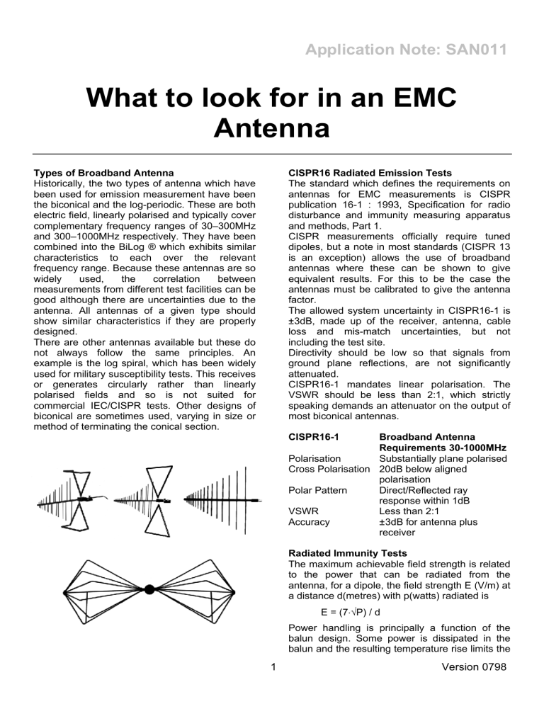
Application Note: SAN011 What to look for in an EMC Antenna Types of Broadband Antenna Historically, the two types of antenna which have been used for emission measurement have been the biconical and the log-periodic. These are both electric field, linearly polarised and typically cover complementary frequency ranges of 30–300MHz and 300–1000MHz respectively. They have been combined into the BiLog ® which exhibits similar characteristics to each over the relevant frequency range. Because these antennas are so widely used, the correlation between measurements from different test facilities can be good although there are uncertainties due to the antenna. All antennas of a given type should show similar characteristics if they are properly designed. There are other antennas available but these do not always follow the same principles. An example is the log spiral, which has been widely used for military susceptibility tests. This receives or generates circularly rather than linearly polarised fields and so is not suited for commercial IEC/CISPR tests. Other designs of biconical are sometimes used, varying in size or method of terminating the conical section. CISPR16 Radiated Emission Tests The standard which defines the requirements on antennas for EMC measurements is CISPR publication 16-1 : 1993, Specification for radio disturbance and immunity measuring apparatus and methods, Part 1. CISPR measurements officially require tuned dipoles, but a note in most standards (CISPR 13 is an exception) allows the use of broadband antennas where these can be shown to give equivalent results. For this to be the case the antennas must be calibrated to give the antenna factor. The allowed system uncertainty in CISPR16-1 is ±3dB, made up of the receiver, antenna, cable loss and mis-match uncertainties, but not including the test site. Directivity should be low so that signals from ground plane reflections, are not significantly attenuated. CISPR16-1 mandates linear polarisation. The VSWR should be less than 2:1, which strictly speaking demands an attenuator on the output of most biconical antennas. CISPR16-1 Broadband Antenna Requirements 30-1000MHz Polarisation Substantially plane polarised Cross Polarisation 20dB below aligned polarisation Polar Pattern Direct/Reflected ray response within 1dB VSWR Less than 2:1 Accuracy ±3dB for antenna plus receiver Radiated Immunity Tests The maximum achievable field strength is related to the power that can be radiated from the antenna, for a dipole, the field strength E (V/m) at a distance d(metres) with p(watts) radiated is E = (7⋅√P) / d Power handling is principally a function of the balun design. Some power is dissipated in the balun and the resulting temperature rise limits the 1 Version 0798 Application Note: SAN011 Antenna Factor The field strength E, is obtained by multiplying the voltage V across the load by the antenna factor AF, allowing the attenuation in the connecting cables. The conversion can be expressed by; power that can be applied. Additionally, good VSWR is essential to minimise the power reflected from the antenna and hence make best use of the capabilities of the power amplifier. For these reasons, many antennas that are designed for radiated emissions test cannot be used for radiated immunity. Low directivity maximises the area that can be covered with a constant field strength. IEC 61000-4-3 mandates a uniform area of field at the position at which the EUT is located. This is partly affected by reflections from the screened room walls but also by the uniformity of coverage of the antenna. To cover a given area, a narrow beamwidth antenna will need to be located further from the EUT. Even if a broadbeam antenna is too close, then different parts of the elements will be at significantly different distances from the EUT and uniformity will suffer. E(dBµV/m) = V(dBµV) + AF(dB/m) Since the noise floor of the measuring instrument (minimum measurable V) is fixed, a good system noise floor (minimum measurable E) depends on a low antenna factor. The graph below shows system noise floor for a typical spectrum analyser and a BiLog antenna. Even with this setup, the noise floor exceeds the Class B limit line for 10m distance. A lower sensitivity antenna makes the problem worse. Desirable features of the antenna factor • Low absolute value - high system sensitivity • No sharp resonances - easy interpolation • Minimum sensitivity to external factors It is becoming common practice to quote an antenna factor which applies to free space conditions and assumes a 50Ω load. The AF changes with proximity to the ground plane and the EUT. Errors due to mutual coupling cannot be avoided but if all test antennas use a similar design they will at least be invariant. Mutual coupling with small EUT’s even at 3m is unlikely to cause errors greater than 1dB. Variation of AF with height above the ground plane is most pronounced in horizontal polarisation and is 2 Version 0798 Application Note: SAN011 typically 1dB at resonance (around 70MHz) falling to 0.5dB above 300MHz for a BiLog or biconical antenna. Errors due to mismatch depend on the match at the receiver input and the antenna VSWR. Variation in the slope of the AF curve due to resonances should be minimised. The AF values must be programmed into the test software which interpolates for a particular frequency, and for minimum error a smooth curve is essential. required for a given field strength. VSWR can be improved by inserting an attenuator pad but this itself absorbs power and reduces sensitivity. VSWR Antenna VSWR (Voltage Standing Wave Ratio) affects two aspects of EMC testing; the accuracy of emission measurements and the power required to perform radiated immunity tests. The mismatch uncertainty on receiver measurements is given by; U(dB) = 20log10 ⋅ ( 1 ± l ΓA l⋅l ΓR l ) where ΓA and ΓR are antenna and receiver reflection coefficients, given by; l Γ l = (VSWR-1) / (VSWR+1) The CISPR16 requirement is for a maximum antenna VSWR of 2:1. This is rarely met in practice below about 80MHz, but with this figure for both antenna and receiver the uncertainty from the above equations is +0.9/-1.0dB. When power is fed to an antenna, some is reflected back to the power source and is dissipated in it. This reduces the power that is radiated from the antenna to generate the required field strength, and also over-stresses the power amplifier; some amplifiers can be damaged by this condition. A VSWR of 3:1 will cause half the power applied to be reflected. The lower the VSWR, the more efficient the antenna (assuming no resistive losses) and hence the less power is 3 Version 0798


