Design and Implementation of Type-II Compensator
in DC-DC Switch-Mode Step-up Power Supply
Arnab Ghosh, Student Member, IEEE, and Subrata Banerjee, Member, IEEE
Department of Electrical Engineering, National Institute of Technology, Durgapur 713209, India.
e-mail: aghosh.ee@gmail.com, bansub2004@rediffmail.com
Abstract—DC-DC power supplies have taken place a prime
role in various fields of engineering applications. Such
applications demand steady, regulated source of voltage
irrespective any changes in line and load. The compensators have
taken place a key role for maintaining the accurate performance
of converters dynamics in DC-DC power supplies. Some DC-DC
power-supplies like boost (step-up), buck-boost etc have a righthalf-plane zero i.e. there is a problem of non-minimum phase, so it
is difficult for the PID controller to exhibit good performance.
For this reason a special kind of classical controller i.e. Type-II
compensator is introduced for obtaining better performance. This
paper describes the designing of a Type-II compensator for a DCDC step-up (boost) power supply.
Keywords—switch-mode-power-supply; step-up converter; nonminimum phase system; Type-II compensator designing;
I.
INTRODUCTION
The DC-DC power supplies have been framed an important
role almost every domain of engineering applications. The
introduction of these kinds of power supplies has increased the
technical and economical qualities with extensive area of
applications from a few tens of watts to several hundreds of
megawatts like as battery chargers, laptop/personal computers,
microcontroller/DSP kit, power systems, telecommunication
system, utility grid, spacecraft, high voltage dc transmission,
adjustable motor drives and many others [1][2].
In the early days, the potential dividers (PD’s) used to take
a key role for control and transfer the dc power from one level
to another level to the load. The operations of the PD’s are
simpler but its applications have been reduced due to several
limitations like as sufficient energy loss, difficulties for
stepping up the load voltage, problems in regulations etc.
That’s why the linear regulators were introduced to make the
system energy efficient. The operating principle of linear
regulators are almost similar to the PD’s, is embedded with
load regulation features and the series resistance is replaced by
solid state device. In linear regulators the solid state device
operates in active zone incurring a significant amount of
power losses across it. So, heat sink is required to dissipate the
generated heat. Due to the presence of heat sinks, and linefrequency transformer the size and the weight of the power
supply is bulky in nature and it is not suitable and economical
for large power applications in terms of energy efficiency. But
in Switch-Mode Power Supplies (SMPS) the solid state device
works like a switch i.e. either completely on or off. When the
switch on, large current flows through it with taking almost
978-1-4799-4445-3/15/$31.00 ©2015 IEEE
zero voltage across it. Similarly for off condition, the voltage
across the switch is high with almost zero current through it.
In both the cases the total power losses across the switch is
almost zero, so there are no conduction losses in switch-mode
power supply. So, energy efficiency is very high (extended up
to 95%) in SMPS.
Over the last decades the technical developments are taken
place by the introduction of different types of controller [8-16]
for achieving fast dynamic responses as well as better reliable
DC-DC switch-mode power supply. Actually the dynamic
performance of the power supply is maintained by the control
scheme i.e. nature of the controllers. There are several
classical controllers like PI, PID controllers; have been
developed over the years to ensure desired performance of the
converter under specific conditions. Some converters like
boost (step-up), buck-boost, and fly-back have a right-halfplane zero (non minimum phase system) [3], so it is difficult
for the normal PID controller to exhibit good performance
with load, line variations and parametric uncertainty. For this
reason Type-controllers [4] are best suited. The state-space
averaging [5-7] methods have been used for mathematical
modelling of converter. The main objective of this paper is to
design Type-II controller for a step-up i.e. boost type power
supply and the closed loop stability analysis of the power
supply in frequency domain.
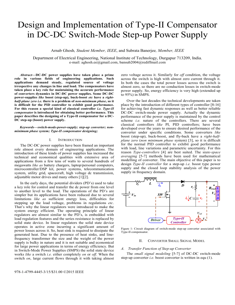
Figure 1: Circuit diagram of switch-mode step-up converter associated with
Type-II compensator.
II.
CONVERTER SMALL SIGNAL MODEL
A. Transfer Function of Step-up Converter
The small signal modeling [5-7] of DC-DC switch-mode
step-up converter i.e. boost converter is written in equ (1).
T ABLE I: P ARAMETERS OF B OOST C ONVERTER
Tp ( s ) =
v0 ( s )
Gdo
d ( s )
⎛
⎞⎛
⎞
s
s
⎜1 +
⎟ ⎜1 −
⎟
⎝ ω z − ESR ⎠ ⎝ ω z − RHP ⎠
⎧⎪
s
s 2 ⎫⎪
+ 2⎬
⎨1 +
⎪⎩ ωo Q ωo ⎪⎭
Circuit Components
(1)
(1 − D )2 ;
Zero due to ESR (ω z − ESR ) = 1 ( rc C ) rad/sec;
where, Gain ( G do ) Vin
RHP Zero (ω z − RHP ) (1 − D )
Natural Freq (ωo ) 2
( Rload − rl )
{r + (1 − D )
l
2
Rload
L rad/sec;
} LCR
load
rad/sec;
Quality Factor ( Q ) = ωo ⎡⎣( rl L ) + {1 C ( Rload + rc )}⎤⎦
From the equ (1), it can be observed that a right-half plane
zero (RHP) present in the converter transfer function. So, there
will be an effect of non-minimum phase problem in converter
dynamics. That’s why the initial under-shoot is coming in
time domain waveform (Figure 2) and bode plot shows the
sufficient phase-lag at gain crossover frequency (Figure 3).
Step Response
1.2
Amplitude
0.6
12 Volt
Inductance L
250 µH
Output Capacitance C
1056 µF
Inductor Resistance rl
10 mΩ
ESR of Capacitor rc
30 mΩ
Load Resistance Rload
25 Ω
Switching Period T
50 µs
III.
)(
(2)
)
where the locations of pole and zero have been considered at
ωp and ωz.
The magnitude of compensator transfer function is found
0
0.005
0.01
0.015
0.02
0.025
Time (seconds)
Tc ( jω ) =
Figure 2: Time response of step-up converter.
Bode Diagram
40
1 + j ω ωz
j ω ω po 1 + j ω ω p
=
1 + (ω ω z )
(
0
Magnitude (dB)
-20
-40
0
)
60
40
20
0
-20
0
Phase (deg)
-90
-180
2
10
4
10
Frequency (rad/s)
Figure 3: Frequency response of boost-converter.
10
6
8
10
-30
-60
-90
1
10
10
2
3
10
4
10
Frequency (rad/s)
Figure 4: The Bode diagram of Type-II compensator
10
5
2
(3)
(4)
Bode Diagram
80
2
(ω ω po ) 1 + (ω ω p )
The argument is written as
arg Tc ( jω ) = tan −1 ( ω ω z ) − tan −1 ω ω p − π
2
20
-270
TYPE-II COMPENSATOR DESIGN
The compensator design is an important part for assuring
good performance and regulation of a power supply. The
compensator, the poles-zeros combinations, is used to provide
the classical loop shaping by modifying the gain and phase
characteristics of open-loop frequency response as well as
ensures the converter robustness. The “Type-II” compensator
is a lead compensator with a pole at origin. So, this
compensator provides 0° to 90° phase boost with zero steady
state error. Even though boost converter having non-minimum
phase system, it exhibits a better closed loop performance
utilizing a cascaded Type-II controller. With proper tuning of
this compensator the converter performs faster response, with
minimal overshoots and zero steady-state error.
(
-0.3
Magnitude (dB)
5 Volt
Output Voltage Vo
The expression of compensator transfer function:
(1 + s ω z )
Tc ( s ) =
s ω po 1 + s ω p
0.3
0
Phase (deg)
Input Voltage Vin
A. Mathematical Approach
Type-II compensator is a pair of pole-zero combination
with a pole at origin.
0.9
-0.6
Values
6
10
The frequency domain response of Type-II compensator is
plotted in Figure 4. Here the combined action of the pole-zero
creates a localized phase boost (70°). If the pole and the zero
coincident, they perfectly neutralize each other i.e. a flat 0-dB
magnitude with 0° phase contribution have found over the
frequency. The phase boost starts again if both of the pole and
zero have been spited together. That’s way the phase lead is to
be varied from 0° to 90° by changing the pole-zero position.
The frequency where the maximum phase boost will be
occurred can easily obtain by derivate equation (4)
d
d
arg Tc ( jω ) ) =
tan −1 ( f f z ) − tan −1 f f p − π
(
2
df
df
(
(
1
)
1
=0
(5)
⎛ f
⎞
⎛ f2
⎞
f z ⎜ 2 + 1⎟ f p ⎜
+ 1⎟
⎜ f
⎟
⎜ f p2
⎟
⎝ z
⎠
⎝
⎠
By solving the equation (5), the maximum phase boost is
obtained at the geometric means of the pole-zero frequencies:
f max = f p f z
(6)
or ,
=
)
−
2
⎛ phase boost π ⎞
f p = k . f c = tan ⎜
+ ⎟ fc
(14)
2
4⎠
⎝
and the zero location will be
f
fc
(15)
fz = c =
k
⎛ phase boost π ⎞
+ ⎟
tan ⎜
2
4⎠
⎝
If the crossover frequency and the necessary phase boost
are known, the compensator pole-zero locations can be easily
found from equ. (14) and (15).
C. Mid-Band Gain Adjustment for the Compensator
Type-II compensator is combination of single pole-zero
pair with an origin pole. Compensator has been described by
equ. (2). Now rewrite the numerator by factoring s/ωz.
ω po 1 + ω z s
(ωz s + 1)
s
=
Tc ( s ) =
ω z s ω po 1 + s ω p
ωz 1 + s ω p
(
or ,
= Go
)(
1 + ωz s
1+ s ωp
)
(16)
Ultimately it can be concluded that the maximum phase
boost is occurred at geometric mean of pole- zero frequencies.
Generally this geometric mean frequency is considered as
crossover frequency of the compensator.
In this expression, ωpo is 0-dB crossover pole and the term
Go is called the mid-band gain and Go is equal to ωpo/ωz.
B. Derivation of k in Type-II Compensator
The ‘k’ is defined as the ratio of the pole frequency to the
zero frequency in Type-II compensator. This pole-zero
combinations provide an adjustable phase boost from 0° to 90°
at the cross over frequency. So equitation should need to find
the relation between k and the phase boost of the compensator.
Let’s assume a power supply that has a gain deficit of - 18
dB at a 1 kHz selected crossover frequency. The necessary
phase boost is 68°. From (14) and (15), a pole can be placed at
⎛ o
⎞
f p == tan ⎜ 68
+ 45o ⎟ ×1000 = 5.14 kHz
(17)
2
⎝
⎠
and the zero is placed at
1000
fz =
= 194.38 Hz
(18)
⎛ 68o
o⎞
+ 45 ⎟
tan ⎜
2
⎝
⎠
So the transfer function of the designed Type-II
1000 ( s + 1221.3)
.
compensator is given by
s ( s + 32324 )
Initially both terms are unknown, so there must be two
equations:
phase boost = tan −1 ( f c f z ) − tan −1 fc f p
(7)
(
and f c = f max =
)
f p fz
(8)
(9)
So, f z = fc2 f p
Now fz is substituted in (7)
phase boost = tan −1 f p f c − tan −1 f c f p
(10)
To solve this equation, k is introduced where k = fp/fz.
⎛1⎞
phase boost = tan −1 ( k ) − tan −1 ⎜ ⎟
(11)
⎝k⎠
From the trigonometric formula
⎛1⎞ π
tan −1 ( k ) + tan −1 ⎜ ⎟ =
(12)
⎝k⎠ 2
By solving k equ. (11) and (12)
(
)
2 tan −1 ( k ) = phase boost +
(
)
π
2
⎛ phase boost π ⎞
or , k = tan ⎜
+ ⎟
(13)
2
4⎠
⎝
The expression has been known as “k factor” approach [4].
So the pole location will be
IV.
DESIGN EXAMPLE WITH A TYPE-II
V.
STABILITY ANALYSIS
A. Closed-loop performances: Adjustment of Compensator
Crossover Frequency (fc)
The closed-loop performances of a step-up (boost)
converter cascaded with Type-II compensator has been studied
with different cross over frequencies (fc) for a constant gain
(Go). Since crossover frequency directly influences the polezero location of compensator, it has to be judiciously selected
to get optimum performance. From Figure 5 & 6 it is clear that
for fc=1 kHz, both the time and frequency responses are better
than fc=300 Hz and fc=2 kHz. It is understood that if the fc is
increased beyond certain value than the performance of the
closed loop converter deteriorates. Again for a lower value of
fc=300 Hz, the time response plot is not impressive and it
exhibits more undershoots before reaching final steady-state
point. The respective comparative performance details are also
reported in T ABLE II.
1.4
Step Responses for Different Crossover Frequencies
B. Closed-loop performance: Adjustment of Compensator
Gain
fc=300 Hz
fc=1000 Hz
fc=2000 Hz
1.2
The closed-loop performances of a step-up power-supply
have been shown in Figure 7 & 8 with different values of
compensator gain for a fixed crossover frequency of 1000 Hz.
Increasing the gain means the damping ratio ξ will be
decreased and consequently the rise time as well as the peak
overshoot may be increased. The comparative analysis of
performance details are also reported in T ABLE III. It can be
observed (from T ABLE III) that the best response is found at
gain (Go) 1000 for cross-over frequency (fc) of 1 kHz.
Amplitude
1
0.8
0.6
0.4
0.2
0
0
0.005
0.01
0.015
0.02
0.025
0.03
Time (seconds)
Phase (deg)
Bode Diagram for Different Crossover Frequencies
1
fc=300 Hz
fc=1000 Hz
fc=2000 Hz
0
-50
Go=500
Go=1000
Go=1500
1.2
Amplitude
Magnitude (dB)
50
Step Responses for Different Gains of Compensator
1.4
Figure 5: The comparative study of closed-loop boost converter for different
cross over frequencies with constant compensator gain.
0.8
0.6
-100
0.4
-150
0
0.2
0
-90
0
0.005
0.01
0.015
0.02
0.025
0.03
0.035
Time (seconds)
-180
-270
1
10
Figure 7: The comparative study of closed-loop boost converter for different
gains of compensator with constant crossover frequency.
2
10
3
10
4
10
10
5
6
7
10
10
Frequency (rad/s)
Figure 6: Bode Diagram of closed-loop boost converter for different cross
over frequencies.
300 Hz
1000 Hz
2000 Hz
Maximum
Overshoot (Mp)
0%
4.52 %
11.2 %
Rise time (tr)
0.0173 sec
0.00324 sec
0.0050 sec
Phase margin
(PM)
63.6°
67.4°
60.7°
699 rad/sec
391 rad/sec
376 rad/sec
19.6 dB
15.8 dB
10.9 dB
2250 rad/sec
1210 rad/sec
896 rad/sec
1000
1000
1000
1000( s + 366.4)
1000( s + 1221.3)
1000( s + 2442.7)
s ( s + 9697.3)
s ( s + 32324)
s ( s + 64648)
Stable
Stable
Stable
Gain crossover
frequency (GCF)
Gain margin
(GM)
Phase Crossover
Frequency (PCF)
Compensator
Gain (Go)
Compensator
Transfer Function
(Tc)
Closed-Loop
Stability
Magnitude (dB)
Crossover
Frequency (fc)
Bode Diagram for Different Gains of Compensator
Go=500
Go=1000
Go=1500
0
-50
-100
-150
360
Phase (deg)
T ABLE II: COMPARITIVE STUDY OF CLOSED-LOOP PERFORMANCES
50
270
180
90
1
10
2
10
10
3
10
4
10
5
10
6
Frequency (rad/s)
Figure 8: Bode Diagram of closed-loop boost converter for different gains of
compensator.
TABLE-III : COMPARITIVE STUDY OF CLOSED-LOOP PERFORMANCES
Compensator Gain
(Go)
500
1000
1500
Crossover
Frequency (fc)
1 kHz
1 kHz
1 kHz
Maximum
Overshoot (Mp)
0%
4.52 %
20.6 %
0.01100 sec
0.00324 sec
0.00232 sec
Rise time (tr)
Phase margin(PM)
81.9°
67.4°
45.7°
Gain crossover
frequency (GCF)
179 rad/sec
391 rad/sec
597 rad/sec
Gain margin (GM)
21.8 dB
15.8 dB
12.3 dB
Phase Crossover
Frequency (PCF)
1210 rad/sec
1210 rad/sec
1210 rad/sec
500( s + 1221.3)
1000( s + 1221.3)
1500( s + 1221.3)
s ( s + 32324)
s ( s + 32324)
s ( s + 32324)
Stable
Stable
Stable
Compensator
Transfer Function
(Tc)
Closed-Loop
Stability
VI.
REFERENCES
[2]
[4]
[5]
[6]
[7]
[8]
[9]
[10]
CONCLUSION
This work describes design of a Type-II compensator for a
DC-DC switch-mode step-up power supply. The cascade
compensated closed loop control system has been simulated in
MATLAB. The effect of crossover frequency (fc) and gain
(Go) on the closed loop stability & performance of converter
has been investigated. These two parameters finally decide the
compensator transfer function. The closed loop behavior of
power supply with Type-II compensation is satisfactory. But
for obtaining better results the parameters of compensator
have to be optimized by soft-computing techniques and this
may be a part of future work.
[1]
[3]
N. Mohan, T. M. Undeland, and W. P. Robbins, “Power Electronics,” 3rd
ed. New York: Wiley, 2003.
M. H Rashid, “Power Electronics – Devices, Circuits and Applications,”
Pearson Publishing, 2014.
[11]
[12]
[13]
[14]
[15]
[16]
K. Ogata, “Modern Control Engineering,” 5th ed. Pearson Education,
India, 2010.
H. Dean Venable, “The k-factor: A New Mathematical Tool for Stability
Analysis and Synthesis,” Proceedings of Powercon 10, CA, March 2224, 1983.
R. D. Middlebrook, and S. Cuk, “A General Unified Approach To
Modelling Switching-Converter Power Stages,” Proceedings of the
IEEE Pwer Electr~nics Specialists Conference, June 1976.
R. D. Middlebrook, “Small-Signal Modeling of Pulse-Width modulated
Switched-Mode Power Converters,” Proceedings of The IEEE, Vol. 76,
No. 4, April 1988.
Y. S. Lee, “Computer-Aided Analysis and Design of Switch-Mode
Power Supplies,” Marcel Dekker, Inc. Hong Kong. 1993.
C. M. Liaw, S. J. Chiang, C.Y. Lai, K.H. Pan, G.C. Leu, and G. S. Hsu,
“Modeling and Controller Design of a Current-Mode Controlled
Converter,”IEEE Transacttons On Industrial Electronics, Vol. 41, No.2,
April 1994.
J. H. Su, J. J. Chen, and D.S. Wu, “Learning Feedback Controller
Design of Switching Converters Via MATLAB/SIMULINK,” IEEE
Transactions On Education, Vol. 45, No. 4, November 2002.
B. Bryant, and M. K. Kazimierczuk, “Modeling the Closed-Current
Loop of PWM Boost DC–DC Converters Operating in CCM With Peak
Current-Mode Control,” IEEE Transactions On Circuits And Systems—
I: Regular Papers, Vol. 52, No. 11, November 2005.
T. Geyer, G. Papafotiou, and M. Morari, “Hybrid Model Predictive
Control of the Step-Down DC-DC Converter,” IEEE Transactions On
Control Systems Technology, Vol. 16, No. 6, November 2008.
K. I. Hwu, and Y. T. Yau, “Performance Enhancement of Boost
Converter Based on PID Controller Plus Linear-to-Nonlinear
Translator,” IEEE Transactions On Power Electronics, Vol. 25, No. 5,
May 2010.
J-K. Kuo and C-F. Wang, "An integrated simulation model for PEM fuel
cell power systems with a buck DC-DC converter," International Journal
of Hydrogen Energy, vol. 36, pp. 11846-11855, 2011.
A. Ghosh, “Nonlinear Dynamics of Power-Factor-Corrected AC-DC
Boost Regulator: Power Converter, Nonlinear Phenomena, Controlling
The Nonlinearity,” LAP Lambert Academic Publishing, 2012.
A. Ghosh, and S. Banerjee, “Design of Type-III Controller for DC-DC
Switch-Mode Boost Converter,” in 6th IEEE Power India International
Conference (PIICON-2014), 5th-7th December 2014, New Delhi, India.
P. Karamanakos, T. Geyer, and S. Manias, “Direct Voltage Control of
DC-DC Boost Converters Using Enumeration-Based Model Predictive
Control,” IEEE Transactions On Power Electronics, Vol. 29, No. 2,
February 2014.
