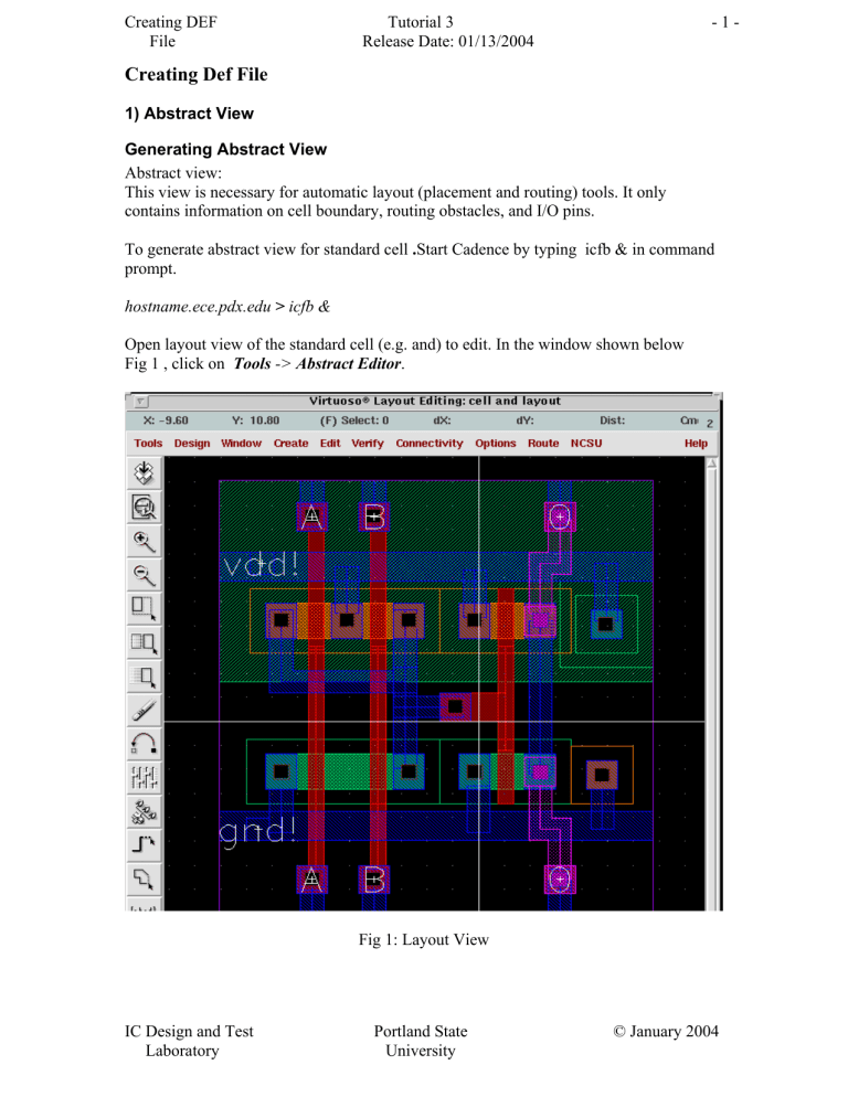
Creating DEF File Tutorial 3 Release Date: 01/13/2004 -1- Creating Def File 1) Abstract View Generating Abstract View Abstract view: This view is necessary for automatic layout (placement and routing) tools. It only contains information on cell boundary, routing obstacles, and I/O pins. To generate abstract view for standard cell .Start Cadence by typing icfb & in command prompt. hostname.ece.pdx.edu > icfb & Open layout view of the standard cell (e.g. and) to edit. In the window shown below Fig 1 , click on Tools -> Abstract Editor. Fig 1: Layout View IC Design and Test Laboratory Portland State University © January 2004 Creating DEF File Tutorial 3 Release Date: 01/13/2004 -2- This brings up Fig 2 as follows. Fig 2: Layout view to generate Abstract Select Abstract -> Set Cell Properties from Fig2. This brings up a “Set Cellview Properties” form ( Fig 3). Make sure that: o o o o Cell Type is Standard Cell Class is none Make Placement Class core as shown in Fig 3. In the Cell Symmetry enable x and y as shown in Fig 3. Then click OK. IC Design and Test Laboratory Portland State University © January 2004 Creating DEF File Tutorial 3 Release Date: 01/13/2004 -3- Fig 3: Set Cellview Properties Select Abstract -> Abgen. This brings out “Create Abstract” form Fig 4 .Fill NCSU Digital_Parts in the Rules Library and abgen.rul in the Rules File. Then click OK as shown in Fig 4. Close the virtuoso window. Fig 4: Create Abstract IC Design and Test Laboratory Portland State University © January 2004 Creating DEF File Tutorial 3 Release Date: 01/13/2004 -4- Go to Library manager and open the abstract view for the standard cell .Then an abstract view will be generated as shown in Fig 5. This is abstract view for the “and”standard cell. Fig 5: Abstract View Repeat this for all standard cells. 2) Creation of Autolayout To create Autolayout of the design we need to perform PR Flatten .This flattens the design. IC Design and Test Laboratory Portland State University © January 2004 Creating DEF File Tutorial 3 Release Date: 01/13/2004 -5- From CIW menu, select File -> Export -> PR Flatten. A “Preview Flatten” form appears. Remember you should perform PR Flatten only on your topmost level cell. Browse to select the Library Name , Cell Name and schematic as View Name as shown in Fig 6 . Make sure Run is Generate Physical Hierarchy. Click OK . This will generate an "AutoLayout" view for the schematic. Fig 6: Preview Flatten The AutoLayout view has unplaced standard cells of the schematic whose AutoLayout has to be generated. 3) Export Def file: From CIW menu, select File -> Export -> DEF. A “Write Cell View to DEF File” form appears. Again browse to get the same top level cell and select autolayout in the view name. Write the DEF File Name as a file with extension .def (for example dl.def) as shown in Fig 7. Click OK. IC Design and Test Laboratory Portland State University © January 2004 Creating DEF File Tutorial 3 Release Date: 01/13/2004 -6- Fig 7: Write Cell View to DEF File DEF File is created. DEF CORRECTION Go to your design directory and run the script def_correction on your def file. This script strips out references to power and ground nets because they are routed differently than normal nets (usually through abutment).Type this command. hostname.ece.pdx.edu > def_correction your_file_name.def > new_file_name.def. Thus the DEF file for your design has been created. Now use Tutorial 5 to do placement and routing using Silicon Ensemble. IC Design and Test Laboratory Portland State University © January 2004

