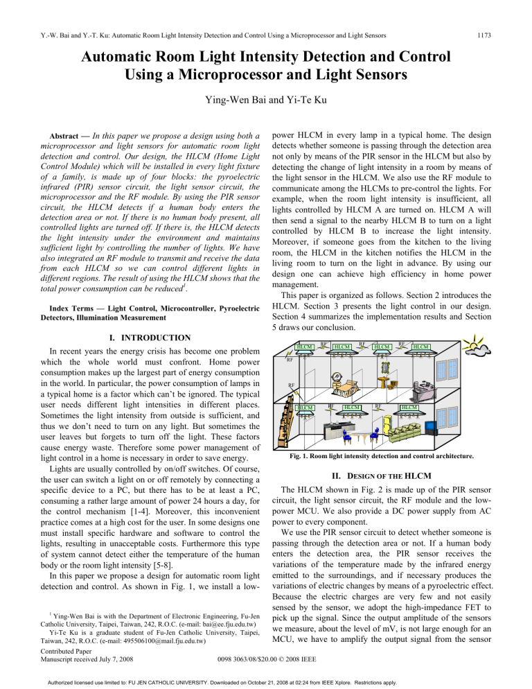
Y.-W. Bai and Y.-T. Ku: Automatic Room Light Intensity Detection and Control Using a Microprocessor and Light Sensors 1173 Automatic Room Light Intensity Detection and Control Using a Microprocessor and Light Sensors Ying-Wen Bai and Yi-Te Ku Abstract — In this paper we propose a design using both a microprocessor and light sensors for automatic room light detection and control. Our design, the HLCM (Home Light Control Module) which will be installed in every light fixture of a family, is made up of four blocks: the pyroelectric infrared (PIR) sensor circuit, the light sensor circuit, the microprocessor and the RF module. By using the PIR sensor circuit, the HLCM detects if a human body enters the detection area or not. If there is no human body present, all controlled lights are turned off. If there is, the HLCM detects the light intensity under the environment and maintains sufficient light by controlling the number of lights. We have also integrated an RF module to transmit and receive the data from each HLCM so we can control different lights in different regions. The result of using the HLCM shows that the total power consumption can be reduced1. Index Terms — Light Control, Microcontroller, Pyroelectric Detectors, Illumination Measurement power HLCM in every lamp in a typical home. The design detects whether someone is passing through the detection area not only by means of the PIR sensor in the HLCM but also by detecting the change of light intensity in a room by means of the light sensor in the HLCM. We also use the RF module to communicate among the HLCMs to pre-control the lights. For example, when the room light intensity is insufficient, all lights controlled by HLCM A are turned on. HLCM A will then send a signal to the nearby HLCM B to turn on a light controlled by HLCM B to increase the light intensity. Moreover, if someone goes from the kitchen to the living room, the HLCM in the kitchen notifies the HLCM in the living room to turn on the light in advance. By using our design one can achieve high efficiency in home power management. This paper is organized as follows. Section 2 introduces the HLCM. Section 3 presents the light control in our design. Section 4 summarizes the implementation results and Section 5 draws our conclusion. I. INTRODUCTION In recent years the energy crisis has become one problem which the whole world must confront. Home power consumption makes up the largest part of energy consumption in the world. In particular, the power consumption of lamps in a typical home is a factor which can’t be ignored. The typical user needs different light intensities in different places. Sometimes the light intensity from outside is sufficient, and thus we don’t need to turn on any light. But sometimes the user leaves but forgets to turn off the light. These factors cause energy waste. Therefore some power management of light control in a home is necessary in order to save energy. Lights are usually controlled by on/off switches. Of course, the user can switch a light on or off remotely by connecting a specific device to a PC, but there has to be at least a PC, consuming a rather large amount of power 24 hours a day, for the control mechanism [1-4]. Moreover, this inconvenient practice comes at a high cost for the user. In some designs one must install specific hardware and software to control the lights, resulting in unacceptable costs. Furthermore this type of system cannot detect either the temperature of the human body or the room light intensity [5-8]. In this paper we propose a design for automatic room light detection and control. As shown in Fig. 1, we install a low1 Ying-Wen Bai is with the Department of Electronic Engineering, Fu-Jen Catholic University, Taipei, Taiwan, 242, R.O.C. (e-mail: bai@ee.fju.edu.tw) Yi-Te Ku is a graduate student of Fu-Jen Catholic University, Taipei, Taiwan, 242, R.O.C. (e-mail: 495506100@mail.fju.edu.tw) Contributed Paper Manuscript received July 7, 2008 HLCM RF HLCM RF HLCM RF HLCM RF RF HLCM RF HLCM RF HLCM Fig. 1. Room light intensity detection and control architecture. II. DESIGN OF THE HLCM The HLCM shown in Fig. 2 is made up of the PIR sensor circuit, the light sensor circuit, the RF module and the lowpower MCU. We also provide a DC power supply from AC power to every component. We use the PIR sensor circuit to detect whether someone is passing through the detection area or not. If a human body enters the detection area, the PIR sensor receives the variations of the temperature made by the infrared energy emitted to the surroundings, and if necessary produces the variations of electric changes by means of a pyroelectric effect. Because the electric charges are very few and not easily sensed by the sensor, we adopt the high-impedance FET to pick up the signal. Since the output amplitude of the sensors we measure, about the level of mV, is not large enough for an MCU, we have to amplify the output signal from the sensor 0098 3063/08/$20.00 © 2008 IEEE Authorized licensed use limited to: FU JEN CATHOLIC UNIVERSITY. Downloaded on October 21, 2008 at 02:24 from IEEE Xplore. Restrictions apply. IEEE Transactions on Consumer Electronics, Vol. 54, No. 3, AUGUST 2008 1174 with a sufficient quantity of two-stage high-gain amplifiers. Nevertheless, if the gain is very high, most tiny noises are amplified simultaneously and interfere seriously with the output signal. Therefore, in our design we have adjusted the value of both the resistance and the capacitance so as not only to amplify the sensed signal and but also to restrain any noise resulting from the temperature variations. R C R C PIR sensor R C C R R C PIR sensor circuit R C R R RR RR R R CR AC power MCU VDD AVDD B0 MCLR B1 A0 A1 C 1M TX OSC1 C RX OSC2 VSS AVSS SSR SSR R R VCC Light sensor VCC R C AC power L T R R R L A. Light controlled by an HLCM As shown in Fig. 4, we install an HLCM at each light. The HLCM detects if a human body is present or not and it detects the light intensity; it switches each light on/off by controlling the SSR on/off to support sufficient light intensity. …… …… VCC III. DESIGN OF THE LIGHT CONTROL BY HLCMS RF module VCC TX VDD RX VSS Power supply circuit VCC D D 7805 D D C C C Light sensor circuit Fig. 2. The circuit diagram of the HLCM. The RF module is specifically designed to connect to the MCU, thus allowing communication to be made among the HLCMs. The modulation of the RF communication is FSK, and the FM modulator works at 2.4 GHz frequency and 2 MKbps speed. The advantages of RF communication are the absence of extra connection wires and its low cost. We have used an SSR to switch each light. SSRs have been utilized to replace mechanical relays because of their many advantages, like miniaturized configuration, little or no contact bounce, low energy consumption, decreased electrical noise, compatibility with digital circuitry and high-speed switching performance. These SSR also provide isolation between a control circuit and a switched circuit. The MCU in the HLCM has three functions, as shown in Fig. 3: to support sufficient light intensity by ascertaining in which room the user is located, detecting the human body, and switching lights on/off by controlling the solid state relays (SSR) on/off. Fig. 3. The control flowchart of the microprocessor. Fig. 4. Light controlled by an HLCM. In our design setting the HLCM measures the average light intensity supported by a light, which is 170 Lux, and the power consumption of a light, which is 80 Watts. When a user turns on all lights, the power consumption increases to 400 Watts. Because there are different levels of sufficient light intensity in different places, the number of lights switched on is different. In Table I we give examples from three different places. TABLE I POWER SAVING IN DIFFERENT PLACES Room Sufficient light intensity Number of lights switched on by HLCM Power consumption Power saving (Watt, %) Living room Bathroom Study room 150 Lux 200 Lux 500 Lux 1 2 3 80 Watts 320 Watts, 80% 160 Watts 240 Watts, 60% 240 Watts 160 Watts, 40% B. The Communication among HLCMs As shown in Fig. 5, we use the RF module to transmit and receive the data from each HLCM in order to pre-control the lights and support sufficient light intensity. If the light intensity is still insufficient for the user when all the lights controlled by HLCM A are turned on, HLCM A will ask the nearest HLCM B to turn on a light controlled by HLCM B to increase the light intensity. Pre-control means that if someone goes from the kitchen to the living room, the HLCM in the kitchen notifies the HLCM in the living room to turn on the light in advance. The communication format has four parts: the address of the HLCM (24 bits), the address of the light devices (5 bits), the status of light (3 bits) and the CRC (Cyclic Redundancy Check, 8 bits). Authorized licensed use limited to: FU JEN CATHOLIC UNIVERSITY. Downloaded on October 21, 2008 at 02:24 from IEEE Xplore. Restrictions apply. Y.-W. Bai and Y.-T. Ku: Automatic Room Light Intensity Detection and Control Using a Microprocessor and Light Sensors Preamble Address Data 1175 Value measured by our design CRC Value measured by digital light meter 3000 D D D D D S S S Illumination (Lux) D Address of lights S Status of lights 00001 Light_1 001 Switch on 00010 Light_2 010 Switch off 00011 Light_3 2500 2000 1500 1000 500 0 Fig. 5. The message format for light control. 0 120 240 360 480 600 720 Time (Minutes) IV. RESULTS OF THE EXPERIMENT Fig. 6 shows the implementation of the HLCM. The hardware prototype circuit of the HLCM is now implemented on an 8 cm × 6 cm printed circuit board (excluding the SSR). The power consumed by the HLCM can be measured and calculated as shown in Table II. We compare the change of the value of light intensity under the same environment between that measured by our design and that of the traditional design measured by a digital light meter. We place a digital light meter 200 cm below a light. Because the HLCM is adjacent to the light, and the light intensity measured by an HLCM is higher than that measured by a digital meter, we have to adjust the value measured by the HLCM to make it similar to that measured by the digital light meter, as shown in Fig. 7. Light sensor PIR sensor Fig. 7. Comparison of the light intensity measured by our design and that measured by a digital light meter. As shown in Fig. 8, we measure the variations of light intensity of three modes for a long time under the same environment. The three modes are the change of light intensity in nature, the change of light intensity when we switch the light on/off by ourselves and the change of light intensity when we install the HLCM at the light. In our experiment we observe the light intensity when in user time; we do not observe the light intensity when in non-user time. Under natural conditions the room light intensity changes along with the outside environment. When we do the switching by ourselves there is one condition: When we switch all lights on because the environment is too dark or when we do not switch the lights off when just leaving for a short time, we maintain enough light intensity. When we switch the lights on/off by using the HLCM, the light intensity is the same as under natural conditions and it is maintained at over 500 Lux if there is a user. When the user leaves the room or the light intensity is more than 1000 Lux, the light is turned off. The change of light intensity in nature The change of light intensity when we switch the lights on/off by ourselves The change of light intensity when we install the HLCM at the light 2500 RF module Fig. 6. Picture of an HLCM. Illumination (Lux) Sunny Cloudy Partly cloudy 2000 1500 1000 TABLE II AVERAGE POWER CONSUMPTION OF THE HLCM MODULE Operation Average Power Average Item Voltage Consumption Current (mA) (V) (W) RF 33 3 0.099 MCU 36 5 0.18 Relay 68 5 0.34 Body 35 5 0.175 Detection Light 38 5 0.19 Detection Total 210 5 or 3 0.984 500 0 0 User time 720 Non-user time 1440 User time 2160 Non-user time Time (Minutes) 2880 User time Non-user time 3600 4320 Fig. 8 The change of room light intensity under three modes. In Fig. 9 we have compared the power consumption between switching the lights on/off by ourselves and using the HLCM. Our measurement confirms that energy is saved by using the HLCM. Authorized licensed use limited to: FU JEN CATHOLIC UNIVERSITY. Downloaded on October 21, 2008 at 02:24 from IEEE Xplore. Restrictions apply. IEEE Transactions on Consumer Electronics, Vol. 54, No. 3, AUGUST 2008 1176 Power consumption (Watts) REFERENCES [1] Switching the lights on/off by ourselves Switching the lights on/off by using the HLCM 300 Sunny 250 Cloudy Partly cloudy 200 [2] 150 100 50 [3] 0 0 720 1440 2160 2880 3600 4320 Time (Minutes) Fig. 9. Comparison of the power consumption of our design with that of other designs. [4] V. CONCLUSION [5] In this paper we have proposed a design for automatic room light detection and control. We install an HLCM at every light of a family for home power management. The HLCM detects if a human body is present or not by using the PIR sensor circuit. If there is no human body present, all lights are turned off. If there is, the HLCM then detects the light intensity under the environment by using the light sensor circuit and the system maintains sufficient room light by switching lights on/off. To realize light intensity support and light pre-control, the RF technology for light power management has been integrated. Consequently, the potential of the features of low cost, small size, low power consumption and power saving has been shown. Table III, a comparison of designs, shows that our design consumes less power, and at a low cost. As a result, our design, which has more integrated functions, is better than others. TABLE III COMPARISON OF OUR DESIGN WITH OTHERS Light Control Design Home Server Power Consumption Body Temperature Detection Light Control Cost Setup Pre-control Light Intensity Setting Support Design 1 Needed 120 Watts Design 2 Needed 25 Watts Our Design Not Needed ≤ 0.984 Watts No No Yes No High Complicated No No No High Easy No No Yes Low Easy Yes Yes [6] [7] [8] Changseok Bae, Jinho Yoo, Kyuchang Kang, Yoonsik Choe, and Jeunwoo Lee, “Home server for home digital service environments”, IEEE International Conference on Consumer Electronics, 2003, vol 49, pp. 1129-1135, Nov. 2003. A. Z. Alkar, and U. Buhur, “An Internet Based Wireless Home Automation System for Multifunctional Devices,” IEEE Transactions on Consumer Electronics, vol. 51, no. 4, pp. 1169-1174, Nov. 2005. Yu-Ping Tsou, Jun-Wei Hsieh, Cheng-Ting Lin, and Chun-Yu Chen, “Building a Remote Supervisory Control Network System for Smart Home Applications,” IEEE International Conference on Systems, Man and Cybernetics, 2006, ICSMC '06, vol. 3, pp. 1826-1830, Oct. 2006. A. R. Al-Ali and M. Al-Rousan, “Java-based home automation system,” IEEE Transactions on Consumer Electronics, vol. 50, no. 2, pp.498-504, May 2004. Chia-Hung Lien, Chi-Hsiung Lin, Ying-Wen Bai, Ming-Fong Liu, and Ming-Bo Lin, “Remotely Controllable Outlet System for Home Power Management,” IEEE Tenth International Symposium on Consumer Electronics, 2006, ISCE/ 2006, pp. 7-12, June 28-July 1, 2006. A. Alheraish, “Design and implementation of home automation system,” IEEE Transactions on Consumer Electronics, vol. 50, no. 4, pp.10871092, Nov. 2004. http://www.iaez.com http://www.homeseer.com Ying-Wen Bai is a professor in the Department of Electronic Engineering at Fu-Jen Catholic University. His research focuses on mobile computing and microcomputer system design. He obtained his M.S. and Ph.D. degrees in electrical engineering from Columbia University, New York, in 1991 and 1993, respectively. Between 1993 and 1995, he worked at the Institute for Information Industry, Taiwan. Yi-Te Ku is currently working toward the M.S. degree in Electronic Engineering at Fu-Jen Catholic University, Taiwan. He received his B.S. degree in electronic engineering from Fu-Jen Catholic University in 2006. His major research is focus on consumer electronics products and microcomputer system integration design. Authorized licensed use limited to: FU JEN CATHOLIC UNIVERSITY. Downloaded on October 21, 2008 at 02:24 from IEEE Xplore. Restrictions apply.


