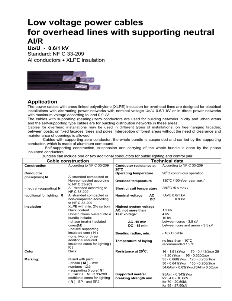
Low voltage power cables for overhead lines with supporting neutral Al/R Uo/U - 0.6/1 kV Standard: NF C 33-209 Al conductors • XLPE insulation Application The power cables with cross-linked polyethylene (XLPE) insulation for overhead lines are designed for electrical installations with alternating power networks with nominal voltage Uo/U 0.6/1 kV or in direct power networks with maximum voltage according to land 0.9 кV. The cables with supporting (bearing) zero conductors are used for building networks in city and urban areas and the self-supporting type cables are for building distribution networks in these areas. Cables for overhead installations may be used in different types of installations: on free hanging facades; between posts; on fixed facades; trees and poles. Interception of forest areas without the need of clearance and maintenance of openings is allowed. -Cables with supporting zero conductor, the whole bundle is suspended and carried by the supporting conductor, which is made of aluminum compound. - Self-supporting construction, suspension and carrying of the whole bundle is done by the phase insulated conductors. Bundles can include one or two additional conductors for public lighting and control pair. Cable construction Construction Conductor phase(main) М - neutral (supporting) N -additional for lighting R Insulation Color Marking: According to NF C 33-209 Al stranded compacted or Non-compacted according to NF C 33-209 AL stranded according to NF C 33-209 Al stranded compacted or non-compacted according to NF C 33-209 XLPE with min. 2% carbon black content Constructions twisted into a bundle include: - phase (main) insulated cores(М) - neutral supporting insulated core ( N ) - one, two, or three additional reduced insulated cores for lighting ( R) black raised with paint: - phase ( М ) – with numbers 1;2;3 - supporting 0 core( N ) ELKABEL NF C 33-209 additional cores for lighting ( R ) - EP1 and EP2 Technical data According to NF C 33-209 Conductor resistance at o 20 C Operating temperature о 90 С continuous operation Overload temperature 130оС /100h/per year мах./ Short circuit temperature 250оС /5 s max./ Nominal voltage Uo/U 0.6/1 kV 0.9 kV АС DC Highest system voltage AC, not more than Test voltage: АC -15 min DC - 15 min 1.2 kV 4 kV 10 kV between cores - 3.5 кV between core and armor - 3.5 кV Bending radius, min. - 18x D cable Temperature of laying no less than - 10оС recommended 15 оС Resistance at 200С: 16 - 1.91 Ω/км 70 - 0.443Ω/км 25 - 1.20 Ω/км 95 - 0.320Ω/км 35 - 0.868Ω/км 120 - 0.253Ω/км 50 - 0.641Ω/км 150 - 0.206Ω/км 54.6Alm - 0.63Ω/км;70Alm- 0.5Ω/км Supported neutral breaking strength min. 95Alm - 0.343Ω/км for 54.6 - 16.6кN for 70 - 20.50kN for 95 - 27.50кN Construction data Al/R 0.6/1 kV Allowed current in distribution networks mm Allowed current in power supply networks А А walls/air/facades kg/km kg/km 1.2 1.4 1.2 1.4 15 18 18 22 - 72 / 93 / 83 95 / 122 / 111 63 / 83 / 75 83 / 111 / 99 91 142 183 285 125 165 260 395 3x25+54.6Alm 3x25+54.6Alm+Kx16 3x35+54.6Alm 3x35+54.6Alm+Kx16 3x50+54.6Alm 3x50+54.6Alm+Kx16 3x50+54.6Alm+Kx25 3x70+54.6Alm 3x70+54.6Alm+Kx16 3x70+54.6Alm+Kx25 1.4/1.6 1.4/1.6/1.2 1.6/1.6 1.6/1.6/1.4 1.6/1.6 1.6/1.6/1.2 1.6/1.6/1.4 1.8/1.6 1.8/1.6/1.2 1.8/1.6/1.4 30 30 33 33 36 36 36 37 40 40 112 112 / 83 138 138 / 83 168 168 / 93 168 / 111 213 213 / 83 213 / 111 - 369 460 455 546 583 674 725 754 845 896 505 635 615 745 725 860 925 950 1080 1150 3x70+70Alm 3x70+70Alm+Kx16 3x70+70Alm+Kx25 1.8/1.5 1.8/1.5/1.2 1.8/1.5/1.4 41 41 41 213 213 / 83 213 / 111 - 798 889 940 984 1115 1185 3x95+54.6Alm 3x95+54.6Alm+Kx16 3x95+54.6Alm+Kx25 1.8/1.6/ 1.8/1.6/1.2 1.8/1.6/1.4 44 44 44 258 258 / 83 258 / 111 - 967 1059 1110 1195 1325 1355 3x95+70Alm 3x95+70Alm+Kx16 3x95+70Alm+Kx25 3x120+70Alm 3x120+70Alm+Kx16 3x120+70Alm+Kx25 1.8/1.5 1.8/1.5/1.2 1.8/1.5/1.4 1.8/1.5 1.8/1.5/1.2 1.8/1.5/1.4 44 44 44 46 46 46 258 258 / 83 258 / 111 300 300 / 83 300 /111 - 1011 1102 1154 1225 4828 1368 1355 1615 1485 1445 1575 1610 3x120+95Alm 3x120+95Alm+Kx16 3x120+95Alm+Kx25 1.8/1.6 1.8/1.6/1.2 1.8/1.6/1.4 47 47 47 300 300 / 83 300 / 111 - 1296 1387 1439 1535 1660 1735 3x150+70Alm 3x150+70Alm+Kx16 3x150+70Alm+Kx25 1.7/1.5/ 1.7/1.5/1.2 1.7/1.5/1.4 48 48 48 344 344 / 83 344 / 111 - 1482 1573 1624 1670 1795 1870 Number of conductors and nominal cross section Thickness of insulation M/N/R Diamete r of bundle approx. n х mm2 mm 2x16 2x25 4x16 4x25 Note: 1. "К" – is the number of conductors for public electricity and can accept values of 0; 1; 2 or 3. 2. Mass of core and cable are shown in К=2 Mass of Аl cores approx. Аl/R Cable weight approx.


