Forged Alloy Pipe Flanges Standard Specification B462
advertisement
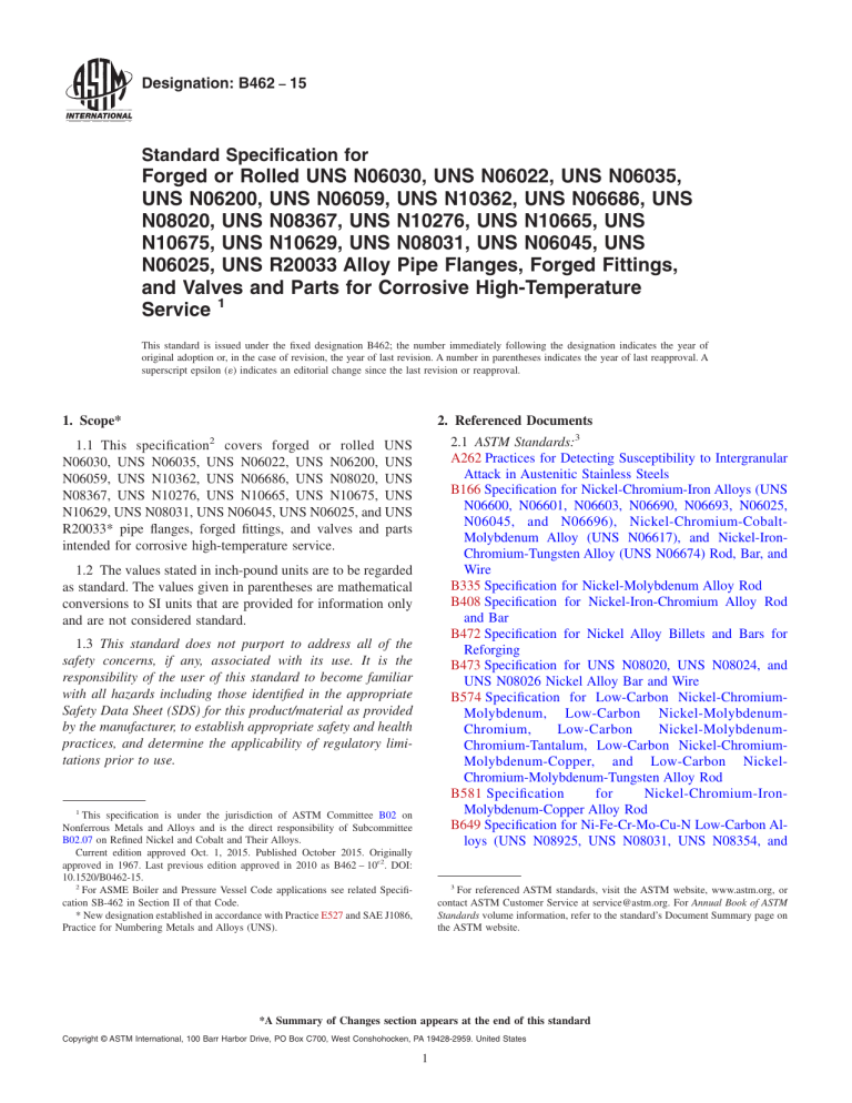
Designation: B462 − 15 Standard Specification for Forged or Rolled UNS N06030, UNS N06022, UNS N06035, UNS N06200, UNS N06059, UNS N10362, UNS N06686, UNS N08020, UNS N08367, UNS N10276, UNS N10665, UNS N10675, UNS N10629, UNS N08031, UNS N06045, UNS N06025, UNS R20033 Alloy Pipe Flanges, Forged Fittings, and Valves and Parts for Corrosive High-Temperature Service 1 This standard is issued under the fixed designation B462; the number immediately following the designation indicates the year of original adoption or, in the case of revision, the year of last revision. A number in parentheses indicates the year of last reapproval. A superscript epsilon (´) indicates an editorial change since the last revision or reapproval. 1. Scope* 2. Referenced Documents 2.1 ASTM Standards:3 A262 Practices for Detecting Susceptibility to Intergranular Attack in Austenitic Stainless Steels B166 Specification for Nickel-Chromium-Iron Alloys (UNS N06600, N06601, N06603, N06690, N06693, N06025, N06045, and N06696), Nickel-Chromium-CobaltMolybdenum Alloy (UNS N06617), and Nickel-IronChromium-Tungsten Alloy (UNS N06674) Rod, Bar, and Wire B335 Specification for Nickel-Molybdenum Alloy Rod B408 Specification for Nickel-Iron-Chromium Alloy Rod and Bar B472 Specification for Nickel Alloy Billets and Bars for Reforging B473 Specification for UNS N08020, UNS N08024, and UNS N08026 Nickel Alloy Bar and Wire B574 Specification for Low-Carbon Nickel-ChromiumMolybdenum, Low-Carbon Nickel-MolybdenumChromium, Low-Carbon Nickel-MolybdenumChromium-Tantalum, Low-Carbon Nickel-ChromiumMolybdenum-Copper, and Low-Carbon NickelChromium-Molybdenum-Tungsten Alloy Rod B581 Specification for Nickel-Chromium-IronMolybdenum-Copper Alloy Rod B649 Specification for Ni-Fe-Cr-Mo-Cu-N Low-Carbon Alloys (UNS N08925, UNS N08031, UNS N08354, and 2 1.1 This specification covers forged or rolled UNS N06030, UNS N06035, UNS N06022, UNS N06200, UNS N06059, UNS N10362, UNS N06686, UNS N08020, UNS N08367, UNS N10276, UNS N10665, UNS N10675, UNS N10629, UNS N08031, UNS N06045, UNS N06025, and UNS R20033* pipe flanges, forged fittings, and valves and parts intended for corrosive high-temperature service. 1.2 The values stated in inch-pound units are to be regarded as standard. The values given in parentheses are mathematical conversions to SI units that are provided for information only and are not considered standard. 1.3 This standard does not purport to address all of the safety concerns, if any, associated with its use. It is the responsibility of the user of this standard to become familiar with all hazards including those identified in the appropriate Safety Data Sheet (SDS) for this product/material as provided by the manufacturer, to establish appropriate safety and health practices, and determine the applicability of regulatory limitations prior to use. 1 This specification is under the jurisdiction of ASTM Committee B02 on Nonferrous Metals and Alloys and is the direct responsibility of Subcommittee B02.07 on Refined Nickel and Cobalt and Their Alloys. Current edition approved Oct. 1, 2015. Published October 2015. Originally approved in 1967. Last previous edition approved in 2010 as B462 – 10ɛ2. DOI: 10.1520/B0462-15. 2 For ASME Boiler and Pressure Vessel Code applications see related Specification SB-462 in Section II of that Code. * New designation established in accordance with Practice E527 and SAE J1086, Practice for Numbering Metals and Alloys (UNS). 3 For referenced ASTM standards, visit the ASTM website, www.astm.org, or contact ASTM Customer Service at service@astm.org. For Annual Book of ASTM Standards volume information, refer to the standard’s Document Summary page on the ASTM website. *A Summary of Changes section appears at the end of this standard Copyright © ASTM International, 100 Barr Harbor Drive, PO Box C700, West Conshohocken, PA 19428-2959. United States 1 B462 − 15 UNS N08926), and Cr-Ni-Fe-N Low-Carbon Alloy (UNS R20033) Bar and Wire, and Ni-Cr-Fe-Mo-N Alloy (UNS N08936) Wire B691 Specification for Iron-Nickel-ChromiumMolybdenum Alloys (UNS N08366 and UNS N08367) Rod, Bar, and Wire B880 Specification for General Requirements for Chemical Check Analysis Limits for Nickel, Nickel Alloys and Cobalt Alloys E8 Test Methods for Tension Testing of Metallic Materials E527 Practice for Numbering Metals and Alloys in the Unified Numbering System (UNS) E1473 Test Methods for Chemical Analysis of Nickel, Cobalt, and High-Temperature Alloys E1916 Guide for Identification of Mixed Lots of Metals 5. Materials and Manufacture 5.1 Discard—A sufficient discard shall be made from each ingot to secure freedom from injurious piping and undue segregation. The material shall have a homogeneous structure as shown by the macroetch test in 7.3. 5.2 Manufacturing Practice: 5.2.1 Material for forging shall consist of a billet, bar, or forging produced in accordance with Specifications B166, B335, B408, B 462, B472, B473, B574, B581, B649, or B691. 5.2.2 The material shall be forged by hammering, pressing, rolling, extruding, or upsetting; it shall be brought as nearly as practicable to the finished shape and size by hot working; and shall be so processed as to cause metal flow during the hot-working operation in the direction most favorable for resisting the stresses encountered in service. 5.2.3 When specified in the order, a sample forging may be sectioned and etched to show flow lines and the condition as regards internal imperfections. In such cases, the question of acceptable and unacceptable character of metal flow shall be a subject for agreement between the manufacturer and the purchaser. 5.2.4 When specified in the order, the manufacturer shall submit for approval of the purchaser a sketch showing the shape of the rough forging before machining. 5.3 Heat Treatment: 5.3.1 The product of UNS N08020 alloy shall be furnished in the stabilized-annealed condition. The product of UNS N06022, UNS N06035, UNS N06030, UNS N06200, UNS N10362, UNS N10276, UNS N10665, UNS N10675, and UNS R20033 alloys shall be furnished in the solution annealed condition. 2.2 ANSI Standard: B16.5 Steel Pipe Flanges and Flanged Fittings (for applicable alloy UNS N08020)4 2.3 Manufacturers’ Standardization Society of the Valve and Fittings Industry Standard: SP-25 Standard Marking System for Valves, Fittings, Flanges, and Unions5 3. Terminology 3.1 Definitions of Terms Specific to This Standard: 3.1.1 forgings, n—the term forgings as used in this specification shall be understood to cover one or all of the products mentioned in 1.1, either forged or rolled. 4. Ordering Information 4.1 It is the responsibility of the purchaser to specify all requirements that are necessary for material ordered under this specification. Examples of such requirements include, but are not limited to, the following: 4.1.1 Quantity (weight or number of pieces), 4.1.2 Name of material or UNS number, 4.1.3 Forging sketch when required (5.2.4), 4.1.4 Forging sectioning, if required (5.2.3), 4.1.5 ASTM designation and year of issue, 4.1.6 Inspection (14.1), 4.1.7 Supplementary requirements, if any, and 4.1.8 If possible, the intended end use. NOTE 2—The recommended annealing temperatures all followed by water quenching or rapidly cooling by other means are: UNS N06030–2125 to 2175°F (1163 to 1191°C), UNS N06022–2025 to 2075°F (1107 to 1135°C), UNS N06035–2025–2075°F (1107–1135°C), UNS N06200–2075 to 2125°F (1135 to 1163°C), UNS N06059–2025 to 2125°F (1107 to 1163°C), UNS N10362–2075 to 2125°F (1135 to 1163°C), UNS N06686–2125 to 2225°F (1163 to 1218°C), UNS N08020–1700 to 1850°F (927 to 1010°C), UNS N10276–2025 to 2075°F (1107 to 1135°C), UNS N10665–1925 to 2000°F (1052 to 1093°C), UNS N10675–1925 to 2000°F (1052 to 1093°C), UNS N10629–1925 to 2000°F (1052 to 1093°C), UNS N08031–2050 to 2160°F (1121 to 1182°C) UNS N06045–2125 to 2190°F (1163 to 1199°C), UNS N06025–2175 to 2240°F (1191 to 1227°C), and UNS R20033–2010 to 2150°F (1100 to 1180°C). 5.3.2 Alloy N08367 shall be furnished in the solution annealed condition. 5.3.2.1 The recommended heat treatment shall consist of heating to a minimum temperature of 2025°F (1105°C) and quenching in water, or rapidly cooling, by other means. 5.3.3 Heat treatment may be performed before machining. NOTE 1—A typical ordering description is as follows: 200 forgings, UNS N08020, in accordance with the attached drawing and Specification B462. 4 Available from American National Standards Institute (ANSI), 25 W. 43rd St., 4th Floor, New York, NY 10036, http://www.ansi.org. 5 Available from Manufacturers Standardization Society of the Valve and Fittings Industry (MSS), 127 Park St., NE, Vienna, VA 22180-4602, http://www.msshq.com. 6. Chemical Composition 6.1 The material shall conform to the requirements as to chemical composition prescribed in Table 1. 2 B462 − 15 TABLE 1 Chemical Requirements Element Carbon, max Manganese, max Phosphorus, max Sulfur, max Silicon, max Nickel Chromium Molybdenum Copper Columbium (Nb) + tantalum Nitrogen Iron Carbon, max Manganese, max Phosphorous, max Sulphur, max Silicon. max Nickel Chromium Molybdenum Copper Columbium (Nb) + tantalum Nitrogen Iron Cobalt, max Tungsten Vanadium, max Titanium, max Zirconium, max Columbium (Nb) Tantalum Nickel + Molybdenum Aluminum, max Carbon, max Manganese, max Phosphorous, max Sulphur, max Silicon, max Nickel, Chromium Molybdenum Copper Yttrium Nitrogen Iron Cobalt, max Tungsten Vanadium, max Titanium, max Zirconium, max Columbium (Nb) Tantalum Cerium Aluminum, max A UNS N08367 UNS R20033 0.07 2.00 0.045 0.035 1.00 32.00–38.00 19.00–21.00 2.00–3.00 3.00–4.00 8 × carbon–1.00 0.030 2.00 0.040 0.030 1.00 23.50 to 25.50 20.00 to 22.00 6.00 to 7.00 0.75 max ... 0.015 2.0 0.02 0.01 0.50 30.0–33.0 31.0–35.0 0.50–2.0 0.30–1.20 ... ... RemainderA 0.18 to 0.25 RemainderA 0.35–0.60 RemainderA Composition, % Element Element UNS N08020 UNS N06030 UNS N06022 UNS N06200 UNS N10276 UNS10665 UNS N10675 0.03 1.5 0.04 0.02 0.8 RemainderA 28.0-31.5 4.0-6.0 1.0-2.4 0.30-1.50 0.015 0.50 0.02 0.02 0.08 RemainderA 20.0-22.5 12.5-14.5 ... ... 0.010 0.50 0.025 0.010 0.08 RemainderA 22.0–24.0 15.0-17.0 0.3-1.9 ... 0.010 1.0 0.04 0.03 0.08 RemainderA 14.5-16.5 15.0-17.0 ... ... 0.02 1.0 0.04 0.03 0.10 RemainderA 1.0 max 26.0-30.0 ... ... 0.01 3.0 0.030 0.010 0.10 RemainderA 1.0-3.0 27.0-32.0 0.20 ... ... 13.0-17.0 5.0 1.5-4.0 ... ... ... ... ... ... ... 2.0-6.0 2.5 2.5-3.5 0.35 ... ... ... ... ... ... 3.0 max 2.0 ... ... ... ... ... ... ... ... 4.0-7.0 2.5 3.0-4.5 0.35 ... ... ... ... ... ... 2.0 max 1.0 ... ... ... ... ... ... ... ... 1.0-3.0 3.0 3.0 max 0.20 0.2 0.10 0.20 max 0.20 max 94.0-98.0 ... ... 0.50 ... ... 0.50 Composition, % UNS N06059 UNS N10362 UNS N06686 UNS N08031 UNS N06045 USN N06025 USN N10629 USN N06035 0.010 0.5 0.015 0.010 0.60 0.025 0.010 0.75 0.04 0.015 2.0 0.020 0.05-0.12 1.0 0.02 0.15-0.25 0.15 0.02 0.01 1.5 0.040 0.050 0.50 0.030 0.010 0.10 RemainderA 22.0-24.0 15.0-16.5 0.50 max ... ... 1.5 max 0.3 ... ... ... ... ... ... ... 0.1-0.4 0.010 0.08 RemainderA 13.8-15.6 21.5-23.0 ... ... ... 1.25 max ... ... ... ... ... ... ... ... 0.50 0.02 0.08 RemainderA 19.0-23.0 15.0-17.0 ... ... ... 5.0 max ... 3.0-4.4 ... 0.02-0.25 ... ... ... ... ... 0.010 0.3 30.0-32.0 26.0-28.0 6.0-7.0 1.0-1.4 ... 0.15-0.25 RemainderA ... ... ... ... ... ... ... ... ... 0.010 2.5-3.0 45.0 min 26.0-29.0 ... 0.3 max ... ... 21.0-25.0 ... ... ... ... ... ... ... 0.03-0.09 ... 0.010 0.5 RemainderA 24.0-26.0 ... 0.1 max 0.05-0.12 ... 8.0–11.0 ... ... ... 0.1-0.2 0.01-0.10 ... ... ... 1.8-2.4 0.010 0.05 RemainderA 0.5-1.5 26.0-30.0 0.5 ... ... 1.0-6.0 2.5 ... ... ... ... ... ... ... 0.1-1.5 0.015 0.60 RemainderA 32.25-34.25 7.60-9.00 0.30 max ... ... 2.00 max 1.00 0.60 max 0.20 ... ... ... ... ... 0.40 Shall be determined arithmetically by difference. 3 B462 − 15 6.2 If a product (check) analysis is performed by the purchaser, the material shall conform to the requirements specified in Table 1 subject to the permissible tolerances in Specification B880. 9. Workmanship, Finish, and Appearance 7. Mechanical Properties and Other Requirements 10. Sampling 7.1 Mechanical Properties—The material shall conform to the requirements as to mechanical properties prescribed in Table 2 at room temperature. 10.1 Lot—Definition: 10.1.1 A lot for chemical analysis shall consist of one heat. 10.1.2 A lot for mechanical properties shall consist of each heat in each heat-treatment charge. 9.1 The forgings shall be uniform in quality and condition, and shall be free of injurious defects. 7.2 Hydrostatic Tests—After machining, valve bodies, fittings, and other pressure-containing parts shall be tested to the hydrostatic shell-test pressures prescribed in ANSI B16.5 for the applicable alloy steel rating for which the forging is designed and shall show no leaks. Forgings ordered under these specifications for working pressures other than those listed in the American National Standard ratings shall be tested to such pressures as may be agreed upon between the manufacturer and the purchaser. 7.2.1 No hydrostatic test is required for welding neck or other flanges. 7.2.2 The forging manufacturer is not required to perform pressure tests on rough forgings that are to be finally machined by others. The fabricator of finished forged parts is not required to pressure-test forgings that are designed to be pressure containing only after assembly by welding into a larger structure. However, the manufacturer of such forgings is responsible as required in accordance with 15.1 for the satisfactory performance of the forgings under the final test required in 7.2. 10.2 Test Material Selection: 10.2.1 Chemical Analysis—Representative samples shall be taken during pouring or subsequent processing. 10.2.1.1 Check analysis, shall be wholly the responsibility of the purchaser. 10.2.2 Mechanical Properties—Samples of the material to provide test specimens shall be taken from such locations in each lot as to be representative of that lot. 11. Number of Tests 11.1 Chemical Analysis—One test per lot. 11.2 Mechanical Properties—One test per lot. 12. Specimen Preparation 12.1 The tension test specimens taken from the forgings, billets, or bars shall be machined to the form and dimensions of the standard 2-in. (50.8-mm) gage length tension test specimen shown in the figure titled Standard 0.500 in. Round Tension Test Specimen with 2 in. Gage Length and Examples of Small-Size Specimens Proportional to the Standard Specimen of Test Methods E8, except as specified in 12.2. 7.3 Macroetch Tests—Etching of tests shall show sound and reasonably uniform material, free of injurious laminations, cracks, segregations, and similar objectionable defects. If, on successive tests, 10 % of any heat fails to pass the requirements of the macroetch test, all forgings from that heat shall be rejected. 12.2 In the case of small sections that will not permit taking the standard test specimen specified in 12.1, the tension test specimen shall be as large as feasible and its dimensions shall be proportional to those shown in the figure titled Standard 0.500 in. Round Tension Test Specimen with 2 in. Gage Length and Examples of Small-Size Specimens Proportional to the 8. Dimensions and Permissible Variations 8.1 The forgings shall conform to the sizes and shapes specified by the purchaser. TABLE 2 Mechanical Property Requirements Tensile Strength, min Yield Strength, min ksi MPa ksi MPa Elongation in 2 in. or 50 mm, min, % 80 95 109 85 100 85 100 100 110 110 100 105 100 94 90 98 110 551 655 750 586 690 586 690 690 760 760 690 725 690 650 620 680 760 35 45 55 35 45 35 45 41 51 51 45 45 45 40 35 39 51 241 310 380 241 310 241 310 283 350 350 310 310 310 276 241 270 350 30.0 30.0 40.0 30 45 30 45 40 40 40 45 40 45 40.0 35 30 40 Alloy UNS UNS UNS UNS UNS UNS UNS UNS UNS UNS UNS UNS UNS UNS UNS UNS UNS N08020 N08367 R20033 N06030 N06022 N06035 N06200 N10276 N10665 N10675 N06059 N10362 N06686 N08031 N06045 N06025 N10629 4 Reduction of Area, min, % 50.0 50.0 ... ... ... ... ... ... ... ... ... ... ... ... ... ... B462 − 15 15. Rejection and Rehearing Standard Specimen of Test Methods E8. The gage length for measuring elongation shall be four times the diameter of the specimen. 15.1 Material that fails to conform to the requirements of this specification may be rejected. Rejection should be reported to the producer or supplier promptly and in writing. In case of dissatisfaction with the results of the test, the producer or supplier may make claim for a rehearing. 12.3 For the purpose of tests, the necessary extra forgings or test bars shall be provided. The test specimen, if cut from a flange, shall be cut tangentially from the flange portion approximately midway between the inner and outer surfaces and approximately midway between the front and back faces. When it is impractical to provide forgings for test purposes, test bars may be made from the billet or bar, provided they are given approximately the same reduction and heat treatment as the forgings. 16. Certification 16.1 When specified in the purchase order or contract, a producer’s or supplier’s certification shall be furnished to the purchaser that the material was manufactured, sampled, tested, and inspected in accordance with this specification and has been found to meet the requirements. When specified in the purchase order or contract, a report of the test results shall be furnished. 13. Tests Methods 13.1 The chemical composition and mechanical properties of the material as enumerated in this specification shall, in case of disagreement, be determined in accordance with the following methods: Test 17.1 Identification marks consisting of the manufacturer’s symbol or name, designation of service rating, the specification, the grade of material, and the size shall be stamped legibly on each forging in accordance with MSS SP-25 and in such position as not to injure the usefulness of the forging. ASTM Designations Chemical analysis Tension A 17. Product Marking E1473A E8 Iron shall be determined arithmetically by difference. 18. Keywords 14. Inspection 18.1 forgings; UNS N06030; UNS N06022; UNS UNS N06200; UNS N06059; UNS N10362; UNS UNS N08020; UNS N08367; UNS N10276; UNS UNS N10675; UNS N10629; UNS N08031; UNS UNS N06025; UNS R20033 14.1 If specified, source inspection of the material by the purchaser at the manufacturer’s plant shall be made as agreed upon between the manufacturer and the purchaser as part of the purchase contract. N06035; N06686; N10665; N06045; SUPPLEMENTARY REQUIREMENTS The following supplementary requirements shall be applied only when specified by the purchaser in the inquiry, contract, or order. nation is a method to assure that no material grade mix-up has happened during manufacturing and marking of the product. S2.2 Product shall receive a Positive Material Identification examination by Guide E1916. S2.3 The quantity examined shall be 100 % of the product. S2.4 All product that is not of the correct material grade shall be rejected. S2.5 The method of product marking after examination shall be agreed upon between the manufacturer and purchaser. S1. Corrosion Tests for UNS N08020 S1.1 One intergranular corrosion test per heat shall be performed by the manufacturer on a sensitized specimen and tested in accordance with Practices A262. When this supplementary requirement is specified, the specific practice (Practice B or Practice E) shall also be specified. If Practice B is specified, the specimen must pass with a rate of less than 0.002 inches per month (ipm). S1.1.1 In addition to the stabilize anneal, the specimen shall be sensitized for 1 h at 1250°F (677°C) before being subjected to corrosion testing. S2. Positive Material Identification Examination S2.1 Product shall receive Positive Material Identification to ensure that the purchaser is receiving product of the correct material grade prior to shipment of the product. This exami- 5 B462 − 15 SUMMARY OF CHANGES Committee B02 has identified the location of selected changes to this standard since the last issue (B462–10ɛ2) that may impact the use of this standard. (Approved October 1, 2015.) (1) Multiple sections and title revised to remove obsolete alloys N08024 and N08026. ASTM International takes no position respecting the validity of any patent rights asserted in connection with any item mentioned in this standard. Users of this standard are expressly advised that determination of the validity of any such patent rights, and the risk of infringement of such rights, are entirely their own responsibility. This standard is subject to revision at any time by the responsible technical committee and must be reviewed every five years and if not revised, either reapproved or withdrawn. Your comments are invited either for revision of this standard or for additional standards and should be addressed to ASTM International Headquarters. Your comments will receive careful consideration at a meeting of the responsible technical committee, which you may attend. If you feel that your comments have not received a fair hearing you should make your views known to the ASTM Committee on Standards, at the address shown below. This standard is copyrighted by ASTM International, 100 Barr Harbor Drive, PO Box C700, West Conshohocken, PA 19428-2959, United States. Individual reprints (single or multiple copies) of this standard may be obtained by contacting ASTM at the above address or at 610-832-9585 (phone), 610-832-9555 (fax), or service@astm.org (e-mail); or through the ASTM website (www.astm.org). Permission rights to photocopy the standard may also be secured from the Copyright Clearance Center, 222 Rosewood Drive, Danvers, MA 01923, Tel: (978) 646-2600; http://www.copyright.com/ 6
