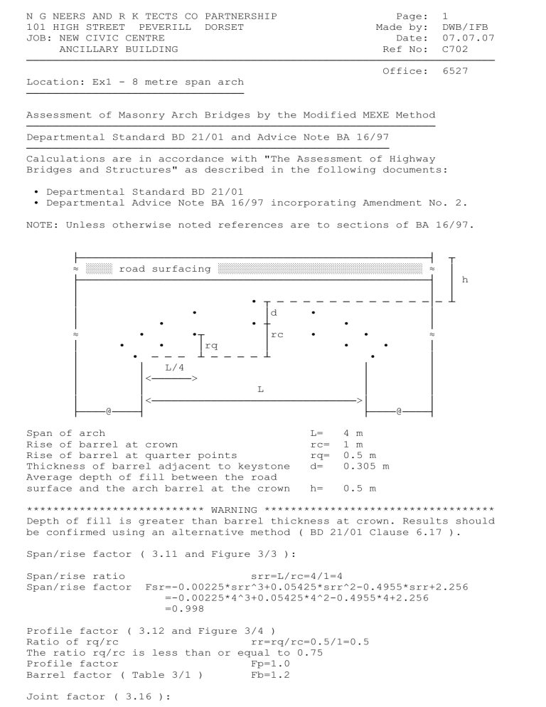
N G NEERS AND R K TECTS CO PARTNERSHIP Page: 1 101 HIGH STREET PEVERILL DORSET Made by: DWB/IFB JOB: NEW CIVIC CENTRE Date: 07.07.07 ANCILLARY BUILDING Ref No: C702 ─────────────────────────────────────────────────────────────────────── Office: 6527 Location: Ex1 - 8 metre span arch ───────────────────────────────── Assessment of Masonry Arch Bridges by the Modified MEXE Method ────────────────────────────────────────────────────────────── Departmental Standard BD 21/01 and Advice Note BA 16/97 ─────────────────────────────────────────────────────── Calculations are in accordance with "The Assessment of Highway Bridges and Structures" as described in the following documents: ■ Departmental Standard BD 21/01 ■ Departmental Advice Note BA 16/97 incorporating Amendment No. 2. NOTE: Unless otherwise noted references are to sections of BA 16/97. ├─────────────────────────────────────────────────────┤ ≈ ░░░░ road surfacing ░░░░░░░░░░░░░░░░░░░░░░░░░░░░░░░ ≈ ├─────────────────────────────────────────────────────┤ │ │ │ ■ ┬ ─ ─ ─ ─ ─ ─ ─ ─ ─ ─ ─ ─│─ │ ■ │d ■ │ │ ■ ■ ┼ ■ │ ≈ ■ ■┬ │rc ■ ■ ≈ │ ■ ■ │rq │ ■ ■ │ │ ■ ─ ─ ─ ┴ ─ ─ ─ ─ ┴ ■ │ │ │ L/4 │ │ │ │<──────> │ │ │ │ L │ │ │ │<───────────────────────────────>│ │ ├────@────┤ ├────@────┤ Span of arch Rise of barrel at crown Rise of barrel at quarter points Thickness of barrel adjacent to keystone Average depth of fill between the road surface and the arch barrel at the crown L= rc= rq= d= 4 m 1 m 0.5 m 0.305 m h= 0.5 m ┬ │ │ h │ ┴ *************************** WARNING *********************************** Depth of fill is greater than barrel thickness at crown. Results should be confirmed using an alternative method ( BD 21/01 Clause 6.17 ). Span/rise factor ( 3.11 and Figure 3/3 ): Span/rise ratio Span/rise factor srr=L/rc=4/1=4 Fsr=-0.00225*srr^3+0.05425*srr^2-0.4955*srr+2.256 =-0.00225*4^3+0.05425*4^2-0.4955*4+2.256 =0.998 Profile factor ( 3.12 and Figure 3/4 ) Ratio of rq/rc rr=rq/rc=0.5/1=0.5 The ratio rq/rc is less than or equal to 0.75 Profile factor Fp=1.0 Barrel factor ( Table 3/1 ) Fb=1.2 Joint factor ( 3.16 ): N G NEERS AND R K TECTS CO PARTNERSHIP Page: 2 101 HIGH STREET PEVERILL DORSET Made by: DWB/IFB JOB: NEW CIVIC CENTRE Date: 07.07.07 ANCILLARY BUILDING Ref No: C702 ─────────────────────────────────────────────────────────────────────── Office: 6527 Joint factor = width factor * mortar factor * depth factor Width factor ( Table 3/3 ) Fw=0.9 Mortar factor ( Table 3/4 ) Fmo=0.9 Pointed joints in good condition. Depth factor ( 3.16 ) Fd=1.0 Gross barrel thickness dr=d=0.305 m Joint factor (3.16 ) Fj=Fw*Fd*Fmo=0.9*1*0.9=0.81 Fill factor ( Table 3/2 ) Ff=0.7 Material Factor ( 3.13 ) = MF (barrel factor*barrel thickness)+(fill factor*fill depth) MF = ───────────────────────────────────────────────────────── total thickness of barrel and fill at crown Material factor Fm=(Fb*dr+Ff*h)/(dr+h) =(1.2*0.305+0.7*0.5)/(0.305+0.5) =0.88944 Condition factor ( 3.17 ) FcM=0.9 Provisional axle load ( 3.10 ) PAL=740*(dr+h)^2/L^1.3 =740*(0.305+0.5)^2/4^1.3 =79.094 tonnes The provisional axle load is limited to 70 tonnes. ( 3.23 ) Revised provisional axle load PAL=70 tonnes The modified axle load represents the allowable loading on the arch from an axle forming part of a double axled bogie configuration with no lift-off from any axle. ( 3.24 ). Modified axle load MAL=Fsr*Fp*Fm*Fj*FcM*PAL =0.998*1*0.88944*0.81*0.9*70 =45.297 tonnes Centrifugal effects not considered. Centrifugal effect factor Fa=1.0 Axle lift-off ( 3.27 ): Axle factors - no lift-off case ( Figure 3/5a ) Single axle Afsanl=TABLE 1 for L=4 =1 Double axle Afdanl=1.0 Triple axle Aftanl=TABLE 2 for L=4 =1 Allowable axle loads - no lift-off case Single axle sanlo=MAL*Afsanl/Fa=45.297*1/1 =45.297 tonnes Double axle danlo=MAL*Afdanl/Fa=45.297*1/1 =45.297 tonnes Triple axle tanlo=MAL*Aftanl/Fa=45.297*1/1 =45.297 tonnes N G NEERS AND R K TECTS CO PARTNERSHIP Page: 3 101 HIGH STREET PEVERILL DORSET Made by: DWB/IFB JOB: NEW CIVIC CENTRE Date: 07.07.07 ANCILLARY BUILDING Ref No: C702 ─────────────────────────────────────────────────────────────────────── Office: 6527 DESIGN SUMMARY ────────────── Allowable axle loads are rounded off to the nearest 0.5 tonnes Rounded values of allowable axle loads - no lift-off case Single axle 45.5 tonnes Double axle 45.5 tonnes Triple axle 45.5 tonnes Weight Restrictions and Permitted Vehicles ( 3.30 ) ┌──────────┬─────────────────────┬───────────┬─────────────╥─────────┐ │ Type of │ Allowable Axle Load │ Max Gross │ Weight ║ Vehicle │ │ Vehicle │ (tonnes) per axle │ Vehicle │ Restriction ║Permitted│ ├──────────┼───────┬──────┬──────┤ Weight │ (tonnes) ║ │ │ │Single │Double│Triple│ (tonnes) │ ║ │ ├──────────┼───────┼──────┼──────┼───────────┼─────────────╫─────────┤ │HGV axles │ │ │ │ │ ║ │ ├──────────┼───────┼──────┼──────┼───────────┼─────────────╫─────────┤ │5 or 6 │ 11.5 │ 10.0 │ 8.0 │ 40/44 │ N/A ║ Yes │ ├──────────┼───────┼──────┼──────┼───────────┼─────────────╫─────────┤ │4 │ 11.5 │ 9.5 │ │ 32 │ 33 ║ Yes │ ├──────────┼───────┼──────┼──────┼───────────┼─────────────╫─────────┤ │3 │ 11.5 │ 9.5 │ │ 26 │ 26 ║ Yes │ ├──────────┼───────┼──────┼──────┼───────────┼─────────────╫─────────┤ │2 │ 11.5 │ │ │ 18 │ 18 ║ Yes │ ├──────────┼───────┼──────┼──────┼───────────┼─────────────╫─────────┤ │2 │ 9.0 │ │ │ 13 │ 13 ║ Yes │ ├──────────┼───────┼──────┼──────┼───────────┼─────────────╫─────────┤ │2 │ 7.0 │ │ │ 10 │ 10 ║ Yes │ ├──────────┼───────┼──────┼──────┼───────────┼─────────────╫─────────┤ │LGV │ 5.5 │ │ │ 7.5 │ 7.5 ║ Yes │ ├──────────┼───────┼──────┼──────┼───────────┼─────────────╫─────────┤ │Car/Van │ 2.0 │ │ │ 3 │ 3 ║ Yes │ ├──────────┼───────┼──────┼──────┼───────────┼─────────────╫─────────┤ │Fire Eng. │ │ │ │ │ ║ │ ├──────────┼───────┼──────┼──────┼───────────┼─────────────╫─────────┤ │Group 1 │ 10.0 │ │ │ │ ║ Yes │ ├──────────┼───────┼──────┼──────┼───────────┼─────────────╫─────────┤ │Group 2 │ 5.0 │ │ │ │ ║ Yes │ └──────────┴───────┴──────┴──────┴───────────┴─────────────╨─────────┘
