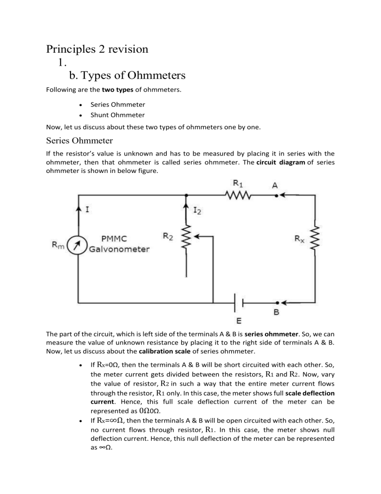
Principles 2 revision 1. b. Types of Ohmmeters Following are the two types of ohmmeters. Series Ohmmeter Shunt Ohmmeter Now, let us discuss about these two types of ohmmeters one by one. Series Ohmmeter If the resistor’s value is unknown and has to be measured by placing it in series with the ohmmeter, then that ohmmeter is called series ohmmeter. The circuit diagram of series ohmmeter is shown in below figure. The part of the circuit, which is left side of the terminals A & B is series ohmmeter. So, we can measure the value of unknown resistance by placing it to the right side of terminals A & B. Now, let us discuss about the calibration scale of series ohmmeter. If Rx=0Ω, then the terminals A & B will be short circuited with each other. So, the meter current gets divided between the resistors, R1 and R2. Now, vary the value of resistor, R2 in such a way that the entire meter current flows through the resistor, R1 only. In this case, the meter shows full scale deflection current. Hence, this full scale deflection current of the meter can be represented as 0Ω0Ω. If Rx=∞Ω, then the terminals A & B will be open circuited with each other. So, no current flows through resistor, R1. In this case, the meter shows null deflection current. Hence, this null deflection of the meter can be represented as ∞Ω. In this way, by considering different values of Rx, the meter shows different deflections. So, accordingly we can represent those deflections with the corresponding resistance value. The series ohmmeter consists of a calibration scale. It has the indications of 0 Ω and ∞Ω at the end points of right hand and left hand of the scale respectively. Series ohmmeter is useful for measuring high values of resistances. Shunt Ohmmeter If the resistor’s value is unknown and to be measured by placing it in parallel (shunt) with the ohmmeter, then that ohmmeter is called shunt ohmmeter. The circuit diagram of shunt ohmmeter is shown in below figure. The part of the circuit, which is left side of the terminals A & B is shunt ohmmeter. So, we can measure the value of unknown resistance by placing it to the right side of terminals A & B. Now, let us discuss about the calibration scale of shunt ohmmeter. Close the switch, S of above circuit while it is in use. If Rx=0Ω, then the terminals A & B will be short circuited with each other. Due to this, the entire current, I1 flows through the terminals A & B. In this case, no current flows through PMMC galvanometer. Hence, the null deflection of the PMMC galvanometer can be represented as 0Ω0Ω. If Rx=∞Ω, then the terminals A & B will be open circuited with each other. So, no current flows through the terminals A & B. In this case, the entire current, I1 flows through PMMC galvanometer. If required vary (adjust) the value of resistor, R1 until the PMMC galvanometer shows full scale deflection current. Hence, this full scale deflection current of the PMMC galvanometer can be represented as ∞Ω In this way, by considering different values of Rx, the meter shows different deflections. So, accordingly we can represent those deflections with the corresponding resistance values. The shunt ohmmeter consists of a calibration scale. It has the indications of 0Ω and ∞Ω at the end points of left hand and right hand of the scale respectively. Shunt ohmmeter is useful for measuring low values of resistances. So, we can use either series ohmmeter or shunt ohmmeter based on the values of resistances that are to be measured i.e., high or low. c. d. When you measure the resistance of an unknown element using a Wheatstone bridge, you need to account for the uncertainty or error in your measurement. This depends on the accuracy and precision of your voltmeter, your source voltage, and your known resistors
