Wireless Communications Homework: Noise Figure & SNR Analysis
advertisement
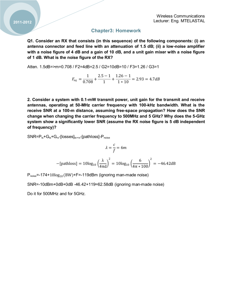
Wireless Communications Lecturer: Eng. MTELASTAL 2011-2012 Chapter3: Homework Q1. Consider an RX that consists (in this sequence) of the following components: (i) an antenna connector and feed line with an attenuation of 1.5 dB; (ii) a low-noise amplifier with a noise figure of 4 dB and a gain of 10 dB, and a unit gain mixer with a noise figure of 1 dB. What is the noise figure of the RX? Atten. 1.5dB=>m=0.708 / F2=4dB=2.5 / G2=10dB=10 / F3=1.26 / G3=1 𝐹𝑒𝑞 = 1 2.5 − 1 1.26 − 1 + + = 2.93 = 4.7𝑑𝐵 0.708 1 1 ∗ 10 2. Consider a system with 0.1-mW transmit power, unit gain for the transmit and receive antennas, operating at 50-MHz carrier frequency with 100-kHz bandwidth. What is the receive SNR at a 100-m distance, assuming free-space propagation? How does the SNR change when changing the carrier frequency to 500MHz and 5 GHz? Why does the 5-GHz system show a significantly lower SNR (assume the RX noise figure is 5 dB independent of frequency)? SNR=Ptx+Gtx+Grx-[losses]tx+rx-[pathloss]-Pnoise 𝜆= − pathloss = 10log10 λ 4πd 𝑐 = 6𝑚 𝑓 2 = 10log10 6 4π ∗ 100 2 = −46.42dB Pnoise=-174+10log10 (BW)+F=-119dBm (ignoring man-made noise) SNR=-10dBm+0dB+0dB -46.42+119=62.58dB (ignoring man-made noise) Do it for 500MHz and for 5GHz.
