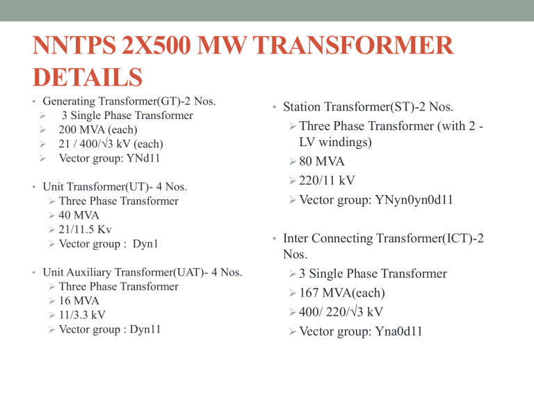
NNTPS 2X500 MW TRANSFORMER DETAILS • Generating Transformer(GT)-2 Nos. 3 Single Phase Transformer 200 MVA (each) 21 / 400/√3 kV (each) Vector group: YNd11 • Unit Transformer(UT)- 4 Nos. Three Phase Transformer 40 MVA 21/11.5 Kv Vector group : Dyn1 • Unit Auxiliary Transformer(UAT)- 4 Nos. Three Phase Transformer 16 MVA 11/3.3 kV Vector group : Dyn11 • Station Transformer(ST)-2 Nos. Three Phase Transformer (with 2 - LV windings) 80 MVA 220/11 kV Vector group: YNyn0yn0d11 • Inter Connecting Transformer(ICT)-2 Nos. 3 Single Phase Transformer 167 MVA(each) 400/ 220/√3 kV Vector group: Yna0d11 TRANSFORMER PROTECTION • Differential Protection • Restricted Earth Fault (REF) Protection • Over flux Protection • HV Backup Protection • LV Backup Protection • Over load function • Buchholz Protection • Pressure Relief Valve(PRV) • High Winding Temperature • Low Oil Level RELAYS AND THEIR PROTECTION FUNCTION • MICOM P643 Differential Earth Fault • MICOM P141 IDMT Overcurrent DT Overcurrent Restricted Earth Fault TRANSFORMER PROTECTION DIFFERENTIAL PROTECTION Fig: Typical Connection Drawing for Differential Relay DIFFERENTIAL PROTECTION • It compares the currents at both sides of • • • • transformer If there is no fault/ through fault, incoming and outgoing currents are equal and there the difference current will be zero. For internal faults, there is difference current and relay operates. For higher stability for through fault currents, percentage differential protection is used. Ratio Correction factor and vector compensation are provided to suitable for different CT ratios and to take care of phase shifting on secondary of PTR DIFFERENTIAL PROTECTION • Difference Current = I1-I2 • Restraining Current = (I1+ I2 )/2 • Slope 1 is provided to take of spill currents due to tap changer • Slope 2 is provided for stability under through fault condition by considering CT saturation • Tripping will be issued based on the difference current with respect to restraining current. DIFFERENTIAL PROTECTION TYPICAL SETTINGS: • I>Diff = 0.10 A to 0.30 A • I>>Diff = 10 A • Slope = 30% to 60% • 2nd harmonic setting = 15% • 5th harmonic setting = 25% RESTRICTED EARTH FAULT (REF) PROTECTION • Faults nearer to neutral of the • • • • power transformers will not covered in the differential protection To take care of the faults in the winding nearer to neutral, REF protection will be provided. It is provided on 400kV power transformers. It compares the neutral current with the vector sum of three phase currents. If the difference current is more than preset value, trip signal will be issued. Fig: REF Connection diagram RESTRICTED EARTH FAULT (REF) PROTECTION • High Impedance Principle is used. • Through fault stability is arrived by Stabilizing Resistor • Stabilizing Resistor Value is calculated by formula • RST= [Ifx (RCT+ 2RL)]/Current Setting • RST= Stabilizing Resistance • RCT= CT Secondary Resistance • RL = Lead Resistance TYPICAL SETTINGS: • Current Setting = 0.02 A • RST= 500 -2500 Ohms Fig: REF Connection diagram OVERFLUX PROTECTION • Flux generated in the transformer is given by • E = 4.44 f ϕ t • ϕ = K.(V/f) • The Over-fluxing condition in a transformer can occur during system over voltage and/or under frequency conditions (V/F) • This will cause an increase in the iron loss and magnetizing current • Under over-excitation, the core bolts which normally carry little flux may be subjected to large component of flux • Under such condition, the bolts may be rapidly heated to a temperature which destroys their own insulation and will damage the coil insulation if the condition continues OVERFLUX PROTECTION OPERATING PRINCIPLE: • It continuously measure the ratio of voltage to frequency. • If the value is higher than preset value, warning or tripping will be issued depending on the operating time. • Two Stages of protection will be provided. One for alarm and one for tripping • Definite Time Setting is used for Alarm • Inverse Characteristic Curve is used for tripping. TYPICAL SETTINGS: For Alarm • V/f setting = 110% of rated V/f • Time Delay = 5 sec For Tripping • V/f setting = 112% of rated V/f • Time Delay = Set to trip in 60 sec at 120% of rated V/f HV & LV BACKUP PROTECTION • Used as backup protection for transformer differential and REF protection. • It also act as backup protection for feeders • Typically, provided with 3 SI IDMT O/C and and 1 SI IDMT E/F relay • Highset Instantaneous element is provided for clear the internal fault in very less time. HV & LV BACKUP PROTECTION • Time of operation shall be typically from 600 ms to 800 ms • Time of operation for SI IDMT relay is given by • ATO = 0.14 x TMS/(PSM)0.02– 1) • Where PSM = fault current/(PS x CTR) • PS = Plug Setting • CTR = CT Ratio OVER LOAD PROTECTION • Continuous over loading may lead to the damage of power transformer. • Over load function is provided to detect the over load condition and issue an alarm signal. • It is typically an over current relay with definite time setting. Typical Setting: • Current Setting= 110% • Time Delay = 5 sec BUCHHOLZ PROTECTION • Provided for sensing slow development of faults inside the transformer • Whenever a fault in transformer develops slowly, heat is produced locally, which begins to decompose solid of liquid insulated materials and produce inflammable gas. • The gas produced get collected inside the relay which acts mercury switch. • It is placed between the main tank and conservator tank. BUCHHOLZ PROTECTION PRV PROTECTION • Internal faults developed inside the transformer produces high pressures inside the transformer. • During this conditions, the pressure inside the PTR shall be release immediately to avoid bulging of main tank and for clear the faults instantaneously. • For this purpose, Pressure Relief Value (PRV) is provided on the main tank. PRESSURE RELIEF VALVE WINDING AND OIL TEMPERATURE INDICATOR • • • Higher load current causes increase in winding temperature It causes failure of insulation material and damages it. Winding Temperature indicator will measure the temperature of oil and issues alarm signal and trip signal at pre-determined settings. • With increase in winding temperature, surrounding oil temperature will also increase. • It causes decomposition of oil and if allows continuously the insulation properties of the oil deteriorate quickly. • Oil Temperature indicator will measure the temperature of oil and issues alarm signal and trip signal at pre-determined settings. Typical Setting: • OT Alarm = 85 C • OT Trip= 95 C • WT Alarm = 90 C Fan Start= 60 C(Winding Temp) • WT Trip= 100 C Fan Stop= 55 C(Winding Temp) OTI AND WTI INDICATORS OIL LEVEL INDICATOR • Entire winding of the power transformer shall be immersed in the oil for proper cooling under low and heavy load conditions • If oil level fall below the core and winding causes increase in its temperature and causes failure of insulation winding • Oil level indicator will measure the level of oil and issues warning/ tripping signal at pre-determined value. OIL LEVEL INDICATOR


