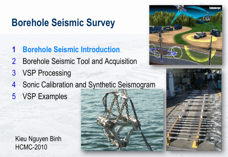
Borehole Seismic Survey 1 2 3 4 5 Borehole Seismic Introduction Borehole Seismic Tool and Acquisition VSP Processing Sonic Calibration and Synthetic Seismogram VSP Examples Kieu Nguyen Binh HCMC-2010 #1 Borehole Seismic Introduction What is Borehole Seismic Survey? A VSP or Vertical Seismic Profile is the process of recording seismic data in a wellbore environment. Vertical Well Zero Offset VSP Survey: Seismic source near the rig (hang by crane) The geophones are vertical in the earth (borehole) At single geophone depth > Source fire > Geophone record signal Record for many geophone depth (VSP level) The seismic ray paths (both direct and reflected rays) are vertical. The direct ray (Downgoing) measures the time-depth information The reflected ray (upgoing) gives a seismic image along the well trajectory. Why run VSP? Well Logs Surface Seismic Data Time Question: Where is my reservoir top on my seismic section? VSP provides Time-Depth curve Reservoir Depth Depth Time VSP Seismic Signal in the Borehole Airgun Source Time Single level Receiver Seismic Events The total signal recorded by the geophone after each firing of the gun is clearly very complex, containing a large number of downgoing and upgoing (reflected) signals. 1 1000m 1500m 1500m 9 5 7 v = 3000m/s d = 2.2 g/cm3 Time Upgoing Downgoing 7 v = 2500m/s 3 d = 2.2 g/cm 4 1000m 6 8 2 8 v = 2000m/s 3 3 d = 2.2 g/cm 11 6 10 11 1 Depth 1 3 10 2 9 5 One-Way Time vs. Two Way Time Surface Seismic VSP TWT = OWT + TT Time Reflection (TWT) TWT Airgun Source TT TT TT OWT Depth TT OWT Downgoing vs Upgoing Wavefield Reflection coefficients INCIDENT REFLECTION COEFFICIENT: REFLECTED Z1 = interface rho1 x vel1 R= Z2 = rho2 x vel2 TRANSMITTED Z2-Z1 Z2+Z1 (Vertical incidence) rho vel Bulk density Velocity Z=rho x vel Acoust Impedance REFLECTED AMPLITUDE = R * INCIDENT AMPLITUDE Usual range within earth < 0.1 Water to Air : R= -1 Examples Water to Limestone : 0.6 Shale to Limestone : < 0.1 Downgoing vs Upgoing Wavefield Relative Amplitude Every level is a stack 3, 5 or more shots. Stacking to increase the signal to noise ratio More complicated example with compressional and shear energy Borehole Seismic Survey Types Ps Pp CHECKSHOT 3D VSP ZERO OFFSET WALKABOVE or VI-VSP CROSS WELL SALT PROX OFFSET WALKAWAY Checkshot Survey Measurements: Geophone position in the borehole coarsely - Small number of levels (50 to 100m level spacing) Measure travel time - Waveform is not used Applications: Time-Depth curve Formation velocity Sonic calibration -> Synthetic Seismogram (Geogram) Depth-to-Time conversion -> Well Tie Zero Offset VSP Measurements: Geophone position in the borehole closely - Large number of levels (15 to 20m spacing) Measure both travel times and waveforms Applications: in addition to applications of checkshot survey 1D Seismic Response - Corridor Stack - Calibration of surface seismic interpretation Look ahead (Over pressure prediction) Multiple pattern identification Q (attenuation) Estimation Phase analysis of surface seismic……..etc Checkshot survey verses VSP survey ~ 100 m level spacing and key depth points A checkshot survey is only interested in the first break time. VSP processing looks are the entire waveform. ~ 20 m level spacing Checkshot verses VSP for Interval Velocity Depth INTV = Delta Delta Time VSP can give a higher resolution interval velocity curve, however, it is limited by the transit time pick accuracy. Other VSP survey types For a Deviated Well VSP (also known as a Vertical Incidence VSP or VI-VSP), the ray path is also vertical, so accurate OWT and TWT values can be derived. It also gives a seismic image below the well trajectory. An offset VSP will have non-vertical ray paths. Nonvertical ray paths are affected by refraction and anisotropy. These effects increase with ray-path angle, and are difficult to correct for. Offset VSP can give a seismic image away from the well path. If accurate time-depth data is required, the survey should have vertical ray paths (VI-VSP or ZO-VSP). The applications of Offset VSP and Walkaway VSP are for seismic imaging. Additional applications for WVSP are anisotropy and AVO measurement. If these surveys are done, then a VI-VSP or ZO-VSP are also normally done in conjunction. Vertical Incident VSP or Walkabove VSP Depth Model Surface Seismic As for Checkshot survey Independent Pp & Ps Seismic answer beneath the well Geophones WALKABOVE Depth (m) Sources Multiple Pattern Identification Time (s) VSP Image Fault and Dip Identification … Offset Source VSP Surface seismic correlation 2D seismic image Lateral extension of reflectors Fault and dip identification Shear wave velocities & imaging Ps Pp OFFSET Walkaway VSP Measurements: Geophone fixed in the borehole Multiple source locations Record reflection around the borehole Application: Surface seismic correlation Fault and dip identification P & S velocities and imaging Anisotropy and AVO analysis Surface survey design Walkaway VSP Common receiver gather Common shot gather One level with walkaway can give an image, but need at least 5 levels to do up-down wavefield separation. Typically use 8 or more simultaneous levels 3D VSP 3-D VSP 3D VSP Well 1 Very High 3D Sub-Surface Imaging Resolution Well 2 Well 1 Well 2 Surface seismic 3D PSDM 3D-VSP Depth Migration Obscured areas All Walkaway applications in a 3D sense … 3D VSP 80m Profile Footprint at Target Plan View Ekofisk 3D VSP Geometry circa 1994 50 “lines” and ~ 10,000 shots 3D-VSP example (2005) 13,400 shots Western Geco source boat Shooting every 10 secs at 5 knots 3.2 km spiral 3D-VSP and 7 Walkaway VSP lines in 48 hours Processing using Q-Borseis software P-wave processing delivered in 6 weeks Riglocation location Rig Borehole Seismic Techniques Wireline Data acquired during a wireline logging operation. – After drilling is completed – During a bit trip – Can be acquired inside drill pipe Borehole Seismic Techniques Drill Bit Seismic Service introduced in the early 1990’s Uses the drill bit as the energy source. Acquires checkshot quality time-depth information in real time. Borehole Seismic Techniques LWD Seismic Service introduced in 2000-2001 Logging tool is in a drillcollar to enable real-time data acquisition. Transit-time data sent up real-time with LWD telemetry. The waveform data is downloaded from memory. LWD Seismic Principle Surface System Surface source Downhole receivers Synchronized clocks Waveforms recorded in downhole memory Downhole processing Real-time check-shot via MWD telemetry Memory data processing after tool pullout Source MWD sea floor SeismicMWD Tool VSP Advantage Record both downgoing waves and upgoing wavefield - Surface seismic survey records only upgoing waves VSP records reflected waves in the downhole Processing can separate down and upgoing wavefield Frequency analysis with borehole depth Q estimation from downgoing wavefield Accurate Time-Depth relationship and Velocity data Primary reflected waves pass the surface weathered layer only once - Less attenuated - Higher frequency content than surface seismic data - Better vertical resolution Multiples are identified Why run VSP more? Here are more questions that VSP could give answers: Is there faults near my borehole? How far my reservoir laterally extend? I want to make synthetic seismograms (sonic calibration) I want to make a velocity model at the well location I need information to better process my surface seismic data Is there over pressured zone below TD?

