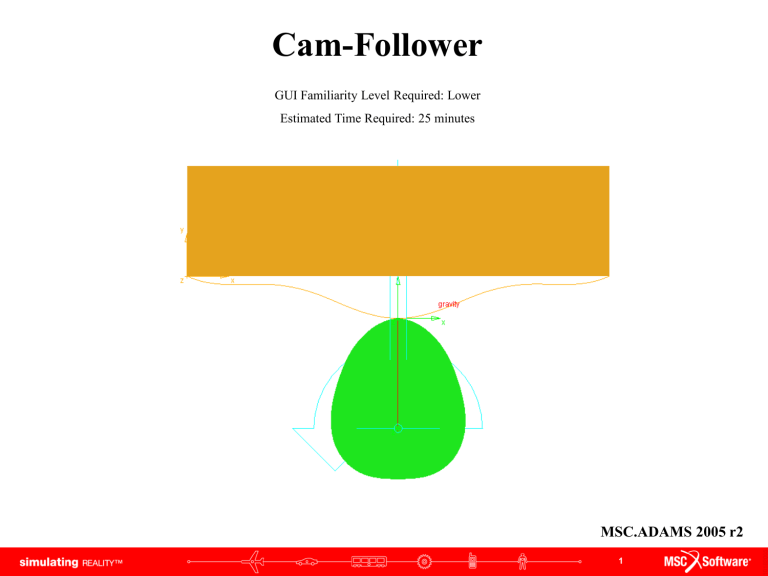
Cam-Follower GUI Familiarity Level Required: Lower Estimated Time Required: 25 minutes MSC.ADAMS 2005 r2 1 Topics Covered In this tutorial you will learn how to: 1. How to manipulate the grid spacing 2. How to create different shapes using the open and closed splines 3. How to add constraints (joints): revolute joint, translational joint and a 2D curve-curve constraint 4. How to create a rigid body: box 5. How to measure 6. How to run simulations 7. How to plot 8. How to save If you have any difficulties, import the “cam_follower_shortcut_1.cmd” file and proceed from pg 10 If you have any difficulties, import the “cam_follower_shortcut_2.cmd” file and proceed from pg 13 If you have any difficulties, import the “cam_follower_complete.cmd” file and proceed from pg 18 2 Cam-Follower Problem The cam mechanism that will be created, analyzed, animated, and plotted in this lab is shown here. Schematic of the Cam Mechanism: The model contains 3 parts (including ground), 1 revolute joint, 1 translational joint, 1 motion, and several markers. 3 What You Should Accomplish If you are successful you should end up with a working ADAMS model that illustrates the movement of a follower along the cam’s contour. 4 Create New Model Getting Started: a. Under the heading "How would you like to proceed", select the Create a new model radio button. b. Choose a Location to save your files c. Choose model_1 as Model Name d. Verify the Gravity text field is set to Earth Normal (-Global Y). e. Verify that the Units text field is set to MMKS - mm,kg,N,s,deg. f. Select OK. a b c d e f 5 Settings To edit the grid size: a. Click Settings menu, then Working Grid… The Working Grid Settings window will appear b. Change the Spacing text fields in X and Y to (10mm) c. Click OK a b c 6 Closed Body Spline Creating an Closed Spline: Cam a. Right-click on the tool stack, click on Spline b. Select New Part from Spline pull down menu c. Turn on checkbox next to Closed. d. Click on the 13 points in the table below. e. Right click on the cam to create a closed spline *Note that the first point and the last point have the same coordinates to create a closed spline. b a c d 7 Closed Body Spline a. An alert box will appear warning you that the part has no mass. Close the box. The complete cam part is created DOWNLOAD FILE *If your part's geometry does not match the illustration, it can be fixed by clicking and dragging any of the "hot points" (rectangular boxes) to its proper location a 8 Create Revolute Joint a. Click Joint tool stack, select Joint: Revolute b. Verify that the Construction text fields read 2 Bod-1 Loc. c. Left-click on any blank area in the working window (ground) d. Left click on your cam e. Click on the position (0,-130,0) A joint between the cam part and the ground is created at that location a c d b e 9 Open Body Spline a. Select the Spline tool b. Turn off the checkbox next to Closed a b c. Click on the 11 points. d. Right click to create the spline. 10 Open Body Spline a. An alert box will appear warning you that the part has no volume. Close the box. The complete part is created DOWNLOAD FILE *If your part's geometry does not match the illustration, it can be fixed by clicking and dragging any of the "hot points" (rectangular boxes) to its proper location a 11 Create Box a. Select the Box tool from the Rigid body tool stack. b. Select Add to Part from Box pull down menu c. Click on the open spline in the ADAMS window to select the part to add to. Now define the corners of the box. d. Click on the left end of the open spline (-250,50,0). e. Click on (250,180,0). e a b d c 12 Create Cylindrical Joint Now create a cylindricall joint between the follower part and the ground part with the axis of translation aligned in the global y direction. a. Select the Joint:Cylindrical tool from the Joint tool stack. b. Verify that the Construction text fields are set to 1 Location and Pick Feature. c. Click on PART_2.cm d. Move the cursor in the positive Global Y axis until an arrow pointing straight up appears. Click once. Make sure the arrow is parallel to the Y axis. This arrow determines the direction of the translational joint. d c a b 13 Create Curve-on-Curve Contact a. Select the Cam (curve-on-curve) contact tool from the Joints button stack. b. Click on the cam part c. Click on the follower c a b 14 Add Rotational Joint Motion Add a rotational motion driver to the revolute joint that specifies a constant cam rotation of one revolution per second. a. Select the Rotational Joint Motion icon from the motion toolbox. b. In the Speed text field, enter (360d) to set the motion displacement to be 360 degrees/second. c. Left-click on the revolute joint (JOINT_1). a b c 15 Verify a. Right-Click on the Information Icon in the bottom right corner of the Working Window b. Left-click on the Verification Icon a b c. After seeing that the model has verified successfully, click on the Close button. c 16 Model This is what your screen should look like when your model is complete 17 Measure a. Right click the follower part and choose measure. The Part Measure dialog box appears. b. Select CM Position from Characteristic pull down menu and select Y for the Component entry to measure the displacement in the Y direction. c. Click Apply. A graph window appears. This is where data will be displayed. d. Repeat, step b & c, except use CM Velocity for Characteristic. e. Repeat, step b & c, except use CM Acceleration for Characteristic. A new graph window will appear for each new measure. f. After the three graph windows are created, click Cancel to close the Part Measure dialog box b a c 18 f Simulation a. Click on the Simulation tool in the Toolbox. b. Enter 1 in End Time text field c. Change Steps to Step Size, enter .01 in the text field d. Click on the Play icon. You should see the cam rotate about the pivot and the follower slide along its translational joint. Corresponding data should be plotted on each graph. e. When the simulation ends, click on the Rewind icon. a e d b c 19 Plotting a. In each of the graph windows, a plot corresponding to each of the measures set earlier appears. b. To get a closer look at a plot, click on a blank area inside the small plot window with the right mouse button and follow the pull right menu. Select Transfer to Full Plot. b c. The ADAMS Plot Window will open, replacing the modeling window. To return to the modeling window, go to the File pull-down menu and select Close Plot Window or press F8 or click on the Return to modeling environment button c 20 Viewing Plots To view other plots: a. Select Objects for the source text field b. Choose a Filter (Body, Force. Constraint) c. Choose an Object d. Choose a Characteristic e. Choose a Component f. Select Surf if you would like to replace the curve in the Plot Window, or select Add Curves to add more curves to the window b c d f e a 21 Saving Return to ADAMS modeling window • Under the File pull-down menu, select Save Database As… a The Save Database As dialog box appears • In the text field next to File Name, enter the name you wish to give this model, for example, cam. • Select OK. b c A binary file (.bin) has been created in the folder you choose when opening ADAMS 22 Topics Covered In this tutorial, you learned how to: 1. manipulate the grid spacing 2. create different shapes using the open and closed splines 3. add constraints (joints): revolute joint, translational joint and a 2D curve-curve constraint 4. create a rigid body: box 5. measure 6. run simulations 7. plot 8. save 23 Best Practices • Make sure correct units are set to mmks. • Make sure the revolute joint is in the z direction. • Make sure translational joint is in the y direction. • Check dimensions of the part to make sure they are correct. • Check locations of spline points to make sure they are correct. • Check orientation of the parts to make sure they are correct. • Verify your model. • Make sure the measures are set correctly. • Make sure the plot is displaying the correct set of results 24 Further Analysis (Optional) Is there any other way to create a cam follower system? Change the cam or follower geometry and see how this will effect the simulations What happens if you move the “hot point” (0,-190,0) on the cam to (0,-180,0) What happens if you move the “hot point” (0,-190,0) on the cam to (0,-230,0) 25


