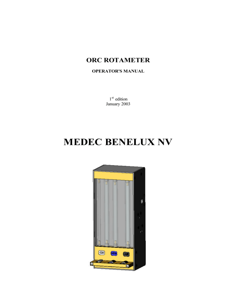
ORC ROTAMETER OPERATOR'S MANUAL 1st edition January 2003 MEDEC BENELUX NV All rights reserved. No part of this publication may be reproduced, stored in a retrieval system or transmitted, in any form or by any means, electronically, mechanically, by photocopying, recording or otherwise, without the prior written permission of Medec Benelux NV. Medec Benelux NV reserves the right to change specifications without prior notification. Careful attention has been paid to the compilation of this publication. Medec Benelux NV Lion D’Orweg 19 9300 Aalst Belgium Telephone : (32) 53 / 70.35.44 Fax : (32) 53 / 70.35.33 Website : www.medecbenelux.be E-mail : sales@medecbenelux.be 1st edition January 2003 Table of Contents 1. General information 1.1 General 1.2 User responsibility 1 1 2. ORC rotameter 2.1 Principle construction 2.2 Pneumatic schema 2.3 25% oxygen safeguard 2.4 Oxygen alarm 2.5 Operation controls 2.6 Flowmeter tubes 2 3 3 3 4 4 4 3. Operation of the uniflow 3.1 Adjustment of the flow 3.2 The 25% safeguard 3.3 Operation of the 25% safety 3.4 Oxygen alarm 3.5 Operation of the alarm 4 5 5 5 6 4. Test procedures 4.1 The test method of the alarm 4.2 The test method of the 25% safeguard 6 7 5. Periodical maintenance and cleaning 5.1 Periodical maintenance and cleaning 7 1. GENERAL INFORMATION 1.1 GENERAL This manual is intended to provide authorized personnel with following information: • • • how to operate the ORC rotameter the operating principles of the system maintenance checks that should be performed Personnel should make themselves familiar with the contents of this manual before using the anesthesia system. 1.2 USER RESPONSIBILITY The equipment described in this manual has been built to conform with the specifications and operating instructions stated in this manual. To ensure proper and safe operation of the equipment, it must be checked and serviced to at least the minimum standards laid out in this manual. The equipment must be repaired and serviced only in accordance with written instructions issued by Medec Benelux NV and must not be altered or modified in any way without written approval of Medec Benelux NV. The user of this equipment shall have the responsibility for any malfunction which results from improper use, maintenance, repair, damage or alteration by anyone other than Medec Benelux NV or its appointed agents. 2. ORC ROTAMETER WARNING: iG If you detect damage to the O-ring of the rotameter or to any connection, do not re-use these parts: significant leakage may occur! ORC rotameter 1 Operator's manual 2.1 PRINCIPLE CONSTRUCTION (Fig.1) 1. Text layer ( fig. 2) The layer is provided with: - logo Medec Benelux N.V. - type flowmeter - place reading point - info regarding alarm situation - info regarding flow adjustment 2. Flowmeter tube Oxygen 0-1 l/min 3. Flowmeter tube Oxygen 0-10 l/min 4. Flowmeter tube N2 O 0-12 l/min 5. Flowmeter tube Air 0-15 l/min 6. Text layer (fig. 3) On the text layer, the codes for the gasses are mentioned: colour code - Oxygen(O2 ) : white RAL 9010 - Nitrous oxide (N 2 O) : blue RAL 5002 - AIR : black/white RAL 9005/9010 7. Control oxygen 8. Control nitrous oxide 9. Control air 10. Control safety guard 11. Outlet nipple 12. Connections 13. Adjustment possibility 25% safeguard 14. Adjustment possibility oxygen alarm 2.2 PNEUMATIC SCHEMA Shows the pneumatisch schema of the Uniflow (fig. 4). The uniflow is standard provided with two safeties, which are operated completely pneumatically : the 25% oxygen safeguard and the oxygen alarm. The desired quantity of oxygen, nitrious oxide and air can be adjusted by means of the controls. The gasses, which are selected with the controls, are collected and mixed at the upper side of the flowmeter tubes. 2.3 25% OXYGEN SAFEGUARD This safety prevents that the patient gets a hypoxic mixture. This situation could occur when the selected oxygen flow is too low or when the nitrous oxide flow is increased without increasing the oxygen flow. This safety provides a minimal oxygen concentration of 25% in the mixture, unregarding the position of the oxygen control. ORC rotameter 2 Operator's manual 2.4 OXYGEN ALARM When the oxygen pressure decreases below half of the working pressure of 1,8 bar, the oxygen alarm becomes operational. At the same time, the nitrous oxide is cut off. It is never possible to give 100% nitrious oxide to the patient. The alarm whistle alarms on the oxygen which is released from the buffer tank. 2.5 OPERATION CONTROLS With the controls, adjustment can be made as desired. Each gas has his own control. Each control has a safety guard, to prevent unintentional adjustments (fig. 5). 2.6 FLOWMETER TUBES Each gas has is own flowmeter tube. The tubes have a gas indication and a scale which indicates how many liters flow through the tube. To prevent static electricity, the tubes are antistatic internally. The rotor is pressed by the upwards pressure of the gas. As the flowmeter tube has a scale, the flow can be read at the upper side of the rotor. WARNING:i For correct reading, the rotor has to rotate ! 3. OPERATION OF THE UNIFLOW 3.1 ADJUSTMENT OF THE FLOW By turning the control spindle, the correct quantity of desired mixture can be set. With the Uniflow, it is possible to give the patient oxygen (O2 ), nitrous oxide (N 2 O) and medical air. The safety guard prevents unintentional adjustments. To increase the flow, the control spindle has to be turned to the left; to decrease to the right (fig. 6). The flowmeter tubes have a scale. The quantity flow is indicated by the rotors in the tubes. ORC rotameter 3 Operator's manual WARNING:i - If you want to increase the total fresh gas flow, first set the O2 higher. - If you want to decrease the total fresh gas flow, first set the N2 O lower. REMARKS: The upperside of the rotor shows the flow in l/min. (fig. 7). WARNING:i For correct reading, the rotor has to rotate ! 3.2 THE 25% SAFEGUARD The block has a membrane system (1) which can open a two-way valve (2), because of a pressure difference between the oxygen and the nitrous oxide pressure. The pneumatic schema of the safety block is shown in fig. 8. 3.3 OPERATION OF THE 25% SAFETY The desired setting can be made with the control spindles of oxygen and nitrous oxide. The set oxygen goes via a restriction (3) to the flowmeter tube. The restriction provides a pressure increase in the 25% adjustment on the right side of the membrane system. The nitrous oxide flows via the valve (5) and the restriction (4) to the nitrous oxide tube. The valve and the restriction provide a pressure increase of nitrous oxide at the right side of the membrane system. The nitrous oxide pressure and the spring press the membrane system to the right while the oxygen pressure presses the membrane system to the left. When the set nitrous oxide is higher, the pressure at the nitrous oxide side becomes higher than the pressure at the oxygen side. Now the two-way valve will open and extra oxygen is given. Because of the extra oxygen supply, the oxygen pressure on the membrane system increases and the two-way valve is closed. The extra oxygen is consumed, so the oxygen pressure decreases. At this moment, extra oxygen is supplied again. In this way, the oxygen concentration stays minimal 25% (fig. 8). 3.4 OXYGEN ALARM According to ISO 5358 standard, an alarm has to be operative in case the oxygen pressure decreases to less than half of the working pressure of 1,8 Bar. The alarm has to sound for at least 7 seconds and the noise level must be minimal 55 dBA. The alarm complies with these requirements. ORC rotameter 4 Operator's manual 3.5 OPERATION OF THE ALARM When the net pressure of oxygen and nitrous oxide are both present, valve C is open and nitrous oxide can flow. Valve B is closed and blocks the gas in the buffer tank (fig. 9). When the net pressure decreases to less than half of the working pressure, the oxygen pressure on valve A becomes lower than the spring pressure and the power caused by the pressure in the buffer tank on valve B. In this case, valve C closes the nitrous oxide and valve B will be opened. The alarm is operative because the buffer tank runs empty via the whistle (fig. 10). At an oxygen and nitrous oxide pressure between 4 and 6 bar, the change-over accuracy is ± 0.3 bar. WARNING:i - At insufficient oxygen pressure, the alarm becomes operative. First set, with the Air control spindle, the quantity air and then locate the cause of the alarm. Resolve the oxygen supply after the whistle signal is over. - Adjustment and maintenance of the flowmeter may only be performed by authorized personnel. 4 TEST PROCEDURES WARNING:i Do not use the flowmeter during testing! 4.1 THE TEST METHOD OF THE ALARM The alarm can be tested as in the following procedure: When there is no extra manometerset foreseen, first mount a manometer to the input pressure of oxygen. - Connect oxygen pressure. - Connect nitrous oxide pressure. - Wait at least 30 seconds. The buffer tank of the alarm is filled now. - Set a nitrous oxide flow of 1 l/min, with the control spindle of nitrous oxide. - Disconnect the oxygen net pressure. - Check if the alarms start to operate when the oxygen pressure is lower than half of the working pressure. At the same time nitrous oxide has to be disconnected. This is if the rotor in the nitrous oxide tube drops to zero. The change-over accuracy is ± 0.3 bar. WARNING:i Please check the alarm before operation! ORC rotameter 5 Operator's manual 4.2 TEST METHOD OF THE 25% SAFEGUARD The 25% safeguard can be tested in following way: - Connect the oxygen pressure. - Connect the nitrous oxide pressure. - Both control spindles of oxygen and nitrous oxide have to be closed. - Set the nitrous oxide flow at 0.7 l/min., via the nitrous oxide control spindle. - Check if the oxygen flow through the oxygen tube is 0.2 l/min. If not, alert your supplier. - Set a nitrous oxide flow of 5 l/min. via the nitrous oxide control spindle. - Check if the oxygen flow through the oxygen tube is 1.5 l/min. If not, alert your supplier. 5 PERIODICAL MAINTENANCE AND CLEANING It is recommendable that the flowmeter is checked during periodical maintenance by the Medec service or by an authorized dealer. 5.1 PERIODICAL MAINTENANCE AND CLEANING It is advisable that the flowmeter is checked once a year by the Medec service, to check its correct operation. The flowmeter can be cleaned externally with a moistured rag. Only use common household cleaning products. The use of aggressive products is NOT recommendable. ORC rotameter 6 Operator's manual Fig 1 ORC rotameter 7 Operator's manual Fig 2 Fig 3 ORC rotameter 8 Operator's manual Fig 4 ORC rotameter 9 Operator's manual Fig 5 Fig 6 ORC rotameter 10 Operator's manual Fig 7 Fig 8 ORC rotameter 11 Operator's manual Fig 9 Fig 10 ORC rotameter 12 Operator's manual
