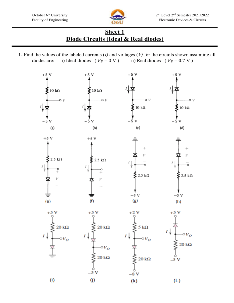
October 6th University Faculty of Engineering 2nd Level 2nd Semester 2021/2022 Electronic Devices & Circuits Sheet 1 Diode Circuits (Ideal & Real diodes) 1- Find the values of the labeled currents (I) and voltages (V) for the circuits shown assuming all diodes are: i) Ideal diodes ( VD = 0 V ) ii) Real diodes ( VD = 0.7 V ) 2- In the circuits shown, find the values of the labeled voltages and currents for: (a) Assuming that the diodes are ideal. (b) Repeat part (a) assuming that the diodes are real. 3- Determine the current and the diode voltage for the circuits shown in each case all diodes are ideal and all diodes are real. Page 2 of 5 4- The diode in the circuit in figure 4 have VD = 0.6 V. Determine the output voltage Vo and the diode currents ID1 and ID2 for the following input conditions: (a) V1 = 10V and V2 = 0V (b) V1 = 5V and V2 = 0V (c) V1 = 10V and V2 = 5V (d) V1 = V2 = 10V 5- In the circuit in figure 5 the diode have VD = 0.6 V. Determine the output voltage Vo and the diode currents ID1 and ID2 for the following input conditions: (a) V1 = V2 = 10V (b) V1 = 10V and V2 = 0V (c) V1 = 10V and V2 = 5V (d) V1 = V2= 0V 6- Let VD = 0.7 V for each diode in the circuit in figure 6. Find ID1 and Vo for R1= 5 KΩ and R2 =10 kΩ 7- For the circuit shown in figure 7, let VD = 0.7 V for each diode. Calculate ID1 and Vo for R1= 10 KΩ and R2 = 5 kΩ Page 3 of 5 8- Determine the current in each diode and the voltage VA and VB in the multi-diode circuit shown in figure 8. Let (a) VD = 0 V and (b) VD = 0.7 V for each diode 9- Find the values of the labeled voltage and current for the circuit shown in the figure 9 assuming: (a) The diodes are ideal. (b) If the forward voltage drop is 0.6V at 1mA. Page 4 of 5 10- Consider a silicon diode with n = 1.5 Find the change voltage if the current changes from 0.1 mA to 10 mA. 11- In the circuit shown in Figure 10 assume that the diode has a voltage of 0.7V at 1mA and the voltage changes by 0.1 V/decade current change. Find ID and VD in case VDD = 5V and R=10KΩ use: (a) Iteration method (b) The piecewise liner model with VD = 0.65V and RD = 20Ω (c) The constant voltage drop model with VD = 0.7V 12- Design the circuit in Figure 11 to provide an output voltage of 2.4V. Assume that the diodes available have 0.7V drop at 1mA and that ∆V= 0.1 V/decade change in current. Page 5 of 5


