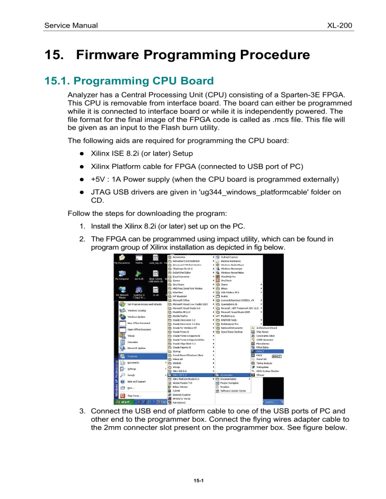
Service Manual XL-200 15. Firmware Programming Procedure 15.1. Programming CPU Board Analyzer has a Central Processing Unit (CPU) consisting of a Sparten-3E FPGA. This CPU is removable from interface board. The board can either be programmed while it is connected to interface board or while it is independently powered. The file format for the final image of the FPGA code is called as .mcs file. This file will be given as an input to the Flash burn utility. The following aids are required for programming the CPU board: Xilinx ISE 8.2i (or later) Setup Xilinx Platform cable for FPGA (connected to USB port of PC) +5V : 1A Power supply (when the CPU board is programmed externally) JTAG USB drivers are given in 'ug344_windows_platformcable' folder on CD. Follow the steps for downloading the program: 1. Install the Xilinx 8.2i (or later) set up on the PC. 2. The FPGA can be programmed using impact utility, which can be found in program group of Xilinx installation as depicted in fig below. 3. Connect the USB end of platform cable to one of the USB ports of PC and other end to the programmer box. Connect the flying wires adapter cable to the 2mm connecter slot present on the programmer box. See figure below. 15-1 Service Manual XL-200 4. Copy the JTAG USB drivers folder given in DVD named"ug344_windows_platformcable" to any location (for e.g.: D drive) on your PC - (D:/ ug344_windows_platformcable/). 5. The first time a cable is attached to pc after installation of Xillinx ISE software, the Found New Hardware Wizard screen appears. 6. Select the first option and click Next. 7. Select the second option to specify the location of the driver. 8. Specify the path where the driver file is unzipped on your local drive. For example: D:/ug344_windows_platformcable/install_xusb/nt/ and then click on Next. 15-2 Service Manual XL-200 9. On clicking, the driver will be automatically installed on your computer. Click Finish to complete the setup. 10. Take the CPU board and put the jumper JP2 between (1-2). Connect a +5V supply to connector J1 (Pin 1: +5V & Pin 2: GND) on CPU board. Connect the flying wires of Programming cable to JTAG pins (J2 header) of the CPU board. (Connector J2 on CPU). The orientation of the cable is as shown in figure below. 11. .Turn the CPU board on. 12. On the start menu go to Programs > Xilinx 8.2i > Accessories > IMPACT for starting the software. 15-3 Service Manual XL-200 13. Select cancel on new project dialogue box. 14. Double click on the Direct SPI Configuration on the left window. Now place the mouse pointer on right side. 15. Right click and choose Add SPI device option (or press Control + D). Now a browse dialogue box will appear. Browse and select the 'mcs' file to be downloaded. See figure below. 16. Select the M25P16 from the part name list box, and then click OK. See figure below. 15-4 Service Manual XL-200 17. On clicking, the FPGA graphical chip will appear with the selected mcs file name. Place the mouse pointer on the graphical chip, right click, and choose Program. See figure below. 18. The Programming Property dialog box will appears. Keep it as default settings, and click OK. See figure below. 19. The CPU board will be successfully programmed if no ERRORS are detected at the end of the verification process. See figure below of impact utility after successful Programming of the CPU board. 15-5 Service Manual XL-200 If any ERRORS are reported during the process, reprogram the CPU using same method. 20. After successful programming process, turn the CPU board off and place the jumper JP2 between (2-3). The CPU board is ready to operate the analyzer logic. Mount it on interface board carefully. 21. Follow the same steps for programming the CPU board connected on interface board, without connecting the power connecter as CPU board gets power from interface board itself. 15.2. Programming PDC and RCT Heater XL-200 analyzer system has a dedicated microcontroller based systems for performing PDC operations and controlling RCT Heater temperature. Following steps will explain programming of these micro-controllers. For programming the micro-controllers, following accessories are required: Flash Programming utility from SiLabs (Given in CD as UtilDLL). USB debug adapter, a Microcontroller Programming Module form SiLabs. USB Cable for connecting PC USB port with USB debug adapter. 2 x 10 Flat Ribbon cable for connecting the microcontroller programming port. PCB connection. 15-6 Service Manual XL-200 Follow the steps for downloading the program: 1. Make the connections with the target board. Make sure that the analyzer is turned OFF while you are making these connections. 2. Run the FlashUtil.exe. 3. On the Silicon Laboratories Flash Utility property sheet, select Connect/Disconnect tab. 4. Define the appropriate parameters as highlighted in the blue box in figure below. Select C2 for RCT and JTAG for old PDC. For PDC board no. ELS62013R4.1 select C2 for both RCT and PDC. 5. Once the appropriate parameters are selected, click Connect. This will make the software connection with the target. 15-7 Service Manual XL-200 6. Select Download Hex File/Go/Stop tab, select the appropriate file from the desired location, and then click Download. 7. On clicking, it takes 20 to 25 seconds to download the program. 8. Turn off the power supply and remove the cable connection with the target board. The board is now ready to use. 15-8


