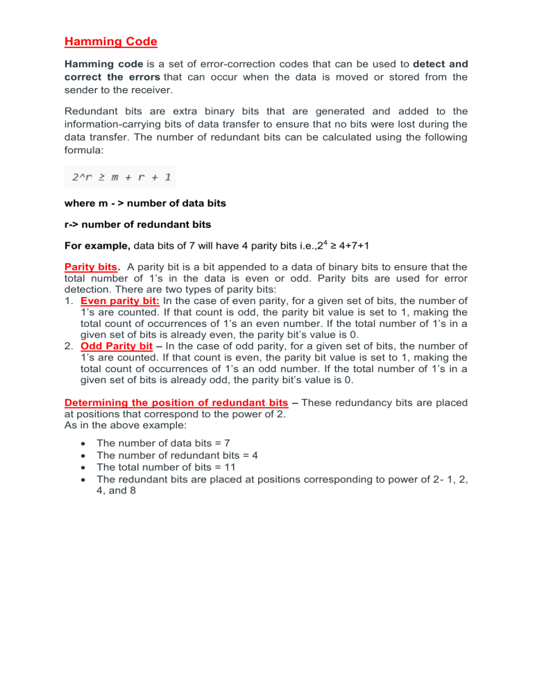
Hamming Code Hamming code is a set of error-correction codes that can be used to detect and correct the errors that can occur when the data is moved or stored from the sender to the receiver. Redundant bits are extra binary bits that are generated and added to the information-carrying bits of data transfer to ensure that no bits were lost during the data transfer. The number of redundant bits can be calculated using the following formula: where m - > number of data bits r-> number of redundant bits For example, data bits of 7 will have 4 parity bits i.e.,24 ≥ 4+7+1 Parity bits. A parity bit is a bit appended to a data of binary bits to ensure that the total number of 1’s in the data is even or odd. Parity bits are used for error detection. There are two types of parity bits: 1. Even parity bit: In the case of even parity, for a given set of bits, the number of 1’s are counted. If that count is odd, the parity bit value is set to 1, making the total count of occurrences of 1’s an even number. If the total number of 1’s in a given set of bits is already even, the parity bit’s value is 0. 2. Odd Parity bit – In the case of odd parity, for a given set of bits, the number of 1’s are counted. If that count is even, the parity bit value is set to 1, making the total count of occurrences of 1’s an odd number. If the total number of 1’s in a given set of bits is already odd, the parity bit’s value is 0. Determining the position of redundant bits – These redundancy bits are placed at positions that correspond to the power of 2. As in the above example: The number of data bits = 7 The number of redundant bits = 4 The total number of bits = 11 The redundant bits are placed at positions corresponding to power of 2- 1, 2, 4, and 8 Hamming Code 1. Write the bit positions starting from 1 in binary form (1, 10, 11, 100, etc). 2. All the bit positions that are a power of 2 are marked as parity bits (1, 2, 4, 8, etc). 3. All the other bit positions are marked as data bits. 4. Each data bit is included in a unique set of parity bits, as determined its bit position in binary form. a. Parity bit 1 covers all the bits positions whose binary representation includes a 1 in the least significant position (1, 3, 5, 7, 9, 11, etc). b. Parity bit 2 covers all the bits positions whose binary representation includes a 1 in the second position from the least significant bit (2, 3, 6, 7, 10, 11, etc). c. Parity bit 4 covers all the bits positions whose binary representation includes a 1 in the third position from the least significant bit (4–7, 12–15, 20–23, etc). d. Parity bit 8 covers all the bits positions whose binary representation includes a 1 in the fourth position from the least significant bit bits (8–15, 24– 31, 40–47, etc). 5. Since we check for even parity set a parity bit to 1 if the total number of ones in the positions it checks is odd. 6. Set a parity bit to 0 if the total number of ones in the positions it checks is even. Determining the Parity bits: Parity bit P1 bit is calculated using parity check at all the bits positions whose binary representation includes a 1 in the least significant position. P1: bits 1, 3, 5, 7, 9, 11 To find the redundant bit R1, we check for even parity. Since the total number of 1’s in all the bit positions corresponding to R1 is an even number the value of P1 (parity bit’s value) = 0 Parity bit P2 bit is calculated using parity check at all the bits positions whose binary representation includes a 1 in the second position from the least significant bit. P2: bits 2,3,6,7,10,11 Parity bit P4 bit is calculated using parity check at all the bits positions whose binary representation includes a 1 in the third position from the least significant bit. P4: bits 4, 5, 6, 7 Parity bit P8 bit is calculated using parity check at all the bits positions whose binary representation includes a 1 in the fourth position from the least significant bit. P8: bit 8,9,10,11 Example Data stream : 1101011 Number of parity bits : 4 i.e., 24 ≥ 4+7+1 … Hamming(7,4) Total bits = 7 + 4 =11 bits Parity bits occupy the positions 1,2,4,8 i.e(20, 21 , 22 ,23) D11 D10 D9 P8 D7 D6 D5 P4 D3 P2 P1 1 1 0 ? 1 0 1 ? 1 ? ? P1 =bits 1,3,5,7,9,11 = P1, 1 ,1, 1, 0, 1 = 0 P2: bits 2,3,6,7,10,11 =P2, 1,0,1,1,1=0 P4: bits 4, 5, 6, 7 = P4,1,0,1 =0 P8: bits 8,9,10,11 = P8,0,1,1 =0 Data stream to store(11 bits) D11 D10 D9 P8 D7 D6 D5 P4 D3 P2 P1 1 1 0 0 1 0 1 0 1 1 0 Error Detection No error: Recalculate the Parity bits, if all parity bits 0, then no error P1 =bits 1,3,5,7,9,11 = 0, 1 ,1, 1, 0, 1 = 0 P2: bits 2,3,6,7,10,11 =0, 1,0,1,1,1=0 P4: bits 4, 5, 6, 7 = 0,1,0,1 =0 P8: bits 8,9,10,11 = 0,0,1,1 =0 The data sequence has no error. With 1 bit error Recalculate the Parity bits. If data is in error, the error position will be returned. Correction will be done by changing the bits accordingly Suppose bit 6 is in error(0 is changed to 1) in the data sequence D11 D10 D9 P8 D7 D6 D5 P4 D3 P2 P1 1 1 0 0 1 1 1 0 1 1 0 Recalculate the parity bits: P1 =bits 1,3,5,7,9,11 = 0, 1 ,1, 1, 0, 1 = 0 P2: bits 2,3,6,7,10,11 =0, 1,1,1,1,1=1 P4: bits 4, 5, 6, 7 = 0,1,1,1 =1 P8: bits 8,9,10,11 = 0,0,1,1 =0 P8P4P2P1 = 0110 = 6. D6 is in error. change the bit from 1 to 0 to correct the error. Then the corrected data is D11 D10 D9 P8 D7 D6 D5 P4 D3 P2 P1 1 1 0 0 1 0 1 0 1 1 0 Cyclic Redundancy CheckModulo 2 Arithmetic Modulo 2 arithmetic is performed digit by digit on binary numbers. Each digit is considered independently from its neighbours. Numbers are not carried or borrowed. Addition/Subtraction Modulo 2 addition/subtraction is performed using an exclusive OR (XOR) operation on the corresponding binary digits of each operand. 0 ± 0 = 0; 0 ± 1 = 1; 1 ± 0 = 1; 1 ± 1 = 0 Cyclic Redundancy Check Cyclic Redundancy Check (CRC) is an error detection method. It is based on binary division. CRC Generator- CRC generator is an algebraic polynomial represented as a bit pattern. Bit pattern is obtained from the CRC generator using the following ruleExampleConsider the CRC generator is x7 + x6 + x4 + x3 + x + 1. Thus, for the given CRC generator, the corresponding binary pattern is 11011011. Steps InvolvedError detection using CRC technique involves the following steps- Step-01: Calculation Of CRC At Sender SideAt sender side, string of n 0’s is appended to the data unit to be transmitted. Here, n is one less than the number of bits in CRC generator. Binary division is performed of the resultant string with the CRC generator. After division, the remainder so obtained is called as CRC. It may be noted that CRC also consists of n bits. Step-02: Appending CRC To Data UnitAt sender side, The CRC is obtained after the binary division. The string of n 0’s appended to the data unit earlier is replaced by the CRC remainder. Step-03: Transmission To Receiver- The newly formed code word (Original data + CRC) is transmitted to the receiver. Step-04: Checking at Receiver SideAt receiver side, The transmitted code word is received. The received code word is divided with the same CRC generator. On division, the remainder so obtained is checked. The following two cases are possible- Case-01: Remainder = 0 If the remainder is zero, Receiver assumes that no error occurred in the data during the transmission. Receiver accepts the data. Case-02: Remainder ≠ 0 If the remainder is non-zero, Receiver assumes that some error occurred in the data during the transmission. Receiver rejects the data and asks the sender for retransmission. CRC Generation CRC Checking Problem-01: A bit stream 1101011011 is transmitted using the standard CRC method. The generator polynomial is x4+x+1. What is the actual bit string transmitted? Solution The generator polynomial G(x) = x4 + x + 1 is encoded as 10011. Clearly, the generator polynomial consists of 5 bits. So, a string of 4 zeroes is appended to the bit stream to be transmitted. The resulting bit stream is 11010110110000. Now, the binary division is performed as- From here, CRC = 1110. Now, The code word to be transmitted is obtained by replacing the last 4 zeroes of 11010110110000 with the CRC. Thus, the code word transmitted to the receiver = 11010110111110. Problem-02: A bit stream 10011101 is transmitted using the standard CRC method. The generator polynomial is x3+1. 1. What is the actual bit string transmitted? 2. Suppose the third bit from the left is inverted during transmission. How will receiver detect this error? SolutionPart-01: The generator polynomial G(x) = x3 + 1 is encoded as 1001. Clearly, the generator polynomial consists of 4 bits. So, a string of 3 zeroes is appended to the bit stream to be transmitted. The resulting bit stream is 10011101000. Now, the binary division is performed as- From here, CRC = 100. Now, The code word to be transmitted is obtained by replacing the last 3 zeroes of 10011101000 with the CRC. Thus, the code word transmitted to the receiver = 10011101100. Part-02: According to the question, Third bit from the left gets inverted during transmission. So, the bit stream received by the receiver = 10111101100. Now, Receiver receives the bit stream = 10111101100. Receiver performs the binary division with the same generator polynomial as- From here, The remainder obtained on division is a non-zero value. This indicates to the receiver that an error occurred in the data during the transmission. Therefore, receiver rejects the data and asks the sender for retransmission. Problem 3: 1. Data unit 1011000 is divided by 1011. 2. During this process of division, whenever the leftmost bit of dividend or remainder is 0, we use a string of Os of same length as divisor. Thus in this case divisor 1011 is replaced by 0000. 3. At the receiver side, data received is 1001110. 4. This data is again divided by a divisor 1011. 5. The remainder obtained is 000; it means there is no error.
