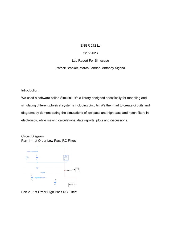
ENGR 212 LJ 2/15/2023 Lab Report For Simscape Patrick Brooker, Marco Landeo, Anthony Sigona Introduction: We used a software called Simulink. It's a library designed specifically for modeling and simulating different physical systems including circuits. We then had to create circuits and diagrams by demonstrating the simulations of low pass and high pass and notch filters in electronics, while making calculations, data reports, plots and discussions. Circuit Diagram: Part 1 - 1st Order Low Pass RC Filter: Part 2 - 1st Order High Pass RC Filter: Part 3 - Notch Pass RC Filter: Part 4 - 3rd Order Low Pass RC Filter: Data: Discussion: 1.Implement a third-order low-pass filter. 2.Tabulate your result according to the datasheet format. 3.Draw the amplitude spectrum of this 3rd order filter and compare its spectrum with that of the first-order filter. 4.Did the cut-off frequency change? Discuss what is the reason for the change? Yes it did, it was a higher order, therefore it filters better.


