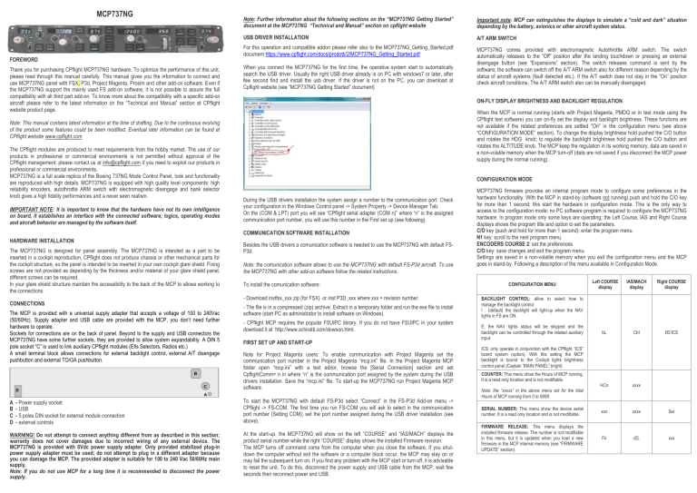
MCP737NG FOREWORD Thank you for purchasing CPflight MCP737NG hardware. To optimize the performance of this unit, please read through this manual carefully. This manual gives you the information to connect and use MCP737NG panel with FSX, P3d, Project Magenta, Prosim and other add-on software. Even if the MCP737NG support the mainly used FS add-on software, it is not possible to assure the full compatibility with all third part add-on. To know more about the compatibility with a specific add-on aircraft please refer to the latest information on the “Technical and Manual” section at CPflight website product page. Note: Further information about the following sections on the “MCP737NG Getting Started” document at the MCP737NG “Technical and Manual” section on cpflight website Important note: MCP can extinguishes the displays to simulate a “cold and dark” situation depending by the battery, avionics or other aircraft system status. USB DRIVER INSTALLATION A/T ARM SWITCH For this operation and compatible addon please refer also to the MCP737NG_Getting_Started.pdf document https://www.cpflight.com/docs/prodotti/2/MCP737NG_Getting_Started.pdf MCP737NG comes provided with electromagnetic Autothrottle ARM switch. The switch automatically releases to the “Off” position after the landing touchdown or pressing an external disengage button (see “Expansions” section). The switch releases command is sent by the software; the software can switch off the A/T ARM switch also for different reason depending by the status of aircraft systems (fault detected etc.). If the A/T switch does not stay in the “On” position check aircraft conditions. The A/T ARM switch also can be manually disengaged. When you connect the MCP737NG for the first time, the operative system start to automatically search the USB driver. Usually the right USB driver already is on PC with windows7 or later, after few second find and install the usb driver. If the driver is not on the PC, you can download at Cpflight website (see “MCP737NG Getting Started” document) ON-FLY DISPLAY BRIGHTNESS AND BACKLIGHT REGULATION When the MCP is normal running (starts with Project Magenta, PMDG or in test mode using the CPflight test software) you can on-fly set the display and backlight brightness. These functions are not available if the related preferences are settled "On" in the configuration menu (see above “CONFIGURATION MODE” section). To change the display brightness hold pushed the C/O button and rotates the HDG knob; to regulate the backlight brightness hold pushed the C/O button and rotates the ALTITUDE knob. The MCP keep the regulation in its working memory, data are saved in a non-volatile memory when the MCP turn-off (data are not saved if you disconnect the MCP power supply during the normal running). Note: This manual contains latest information at the time of drafting. Due to the continuous evolving of the product some features could be been modified. Eventual later information can be found at CPflight website www.cpflight.com The CPflight modules are produced to meet requirements from the hobby market. The use of our products in professional or commercial environments is not permitted without approval of the CPflight management; please contact us at info@cpflight.com if you need to exploit our products in professional or commercial environments. MCP737NG is a full scale replica of the Boeing 737NG Mode Control Panel, look and functionality are reproduced with high details. MCP737NG is equipped with high quality level components: high reliability encoders, autothrottle ARM switch with electromagnetic disengage and bank selector knob gives a high fidelity performances and a never seen realism. IMPORTANT NOTE: It is important to know that the hardware have not its own intelligence on board, it establishes an interface with the connected software; logics, operating modes and aircraft behavior are managed by the software itself. The MCP737NG is designed for panel assembly. The MCP737NG is intended as a part to be inserted in a cockpit reproduction, CPflight does not produce chassis or other mechanical parts for the cockpit structure, so the panel is intended to be inserted in your own cockpit glare shield. Fixing screws are not provided as depending by the thickness and/or material of your glare shield panel, different screws can be required. In your glare shield structure maintain the accessibility to the back of the MCP to allows working to the connections. CONNECTIONS The MCP is provided with a universal supply adapter that accepts a voltage of 100 to 240Vac (50/60Hz). Supply adapter and USB cable are provided with the MCP, you don’t need further hardware to operate. Sockets for connections are on the back of panel. Beyond to the supply and USB connectors the MCP737NG have some further sockets, they are provided to allow system expandability. A DIN 5 pole socket “C” is used to link auxiliary CPflight modules (Efis Selectors, Radios etc.) A small terminal block allows connections for external backlight control, external A/T disengage pushbutton and external TO/GA pushbutton. B C A A B C D During the USB drivers installation the system assign a number to the communication port. Check your configuration in the Windows Control panel -> System Property -> Device Manager Tab. On the (COM & LPT) port you will see “CPflight serial adapter (COM n)” where “n” is the assigned communication port number, you will use this number in the First set up (see following). COMMUNICATION SOFTWARE INSTALLATION HARDWARE INSTALLATION D CONFIGURATION MODE - Power supply socket - USB - 5 poles DIN socket for external module connection - external controls WARNING! Do not attempt to connect anything different from as described in this section; warranty does not cover damages due to incorrect wiring of any external device. The MCP737NG is provided with 6Vdc power supply adapter. Only provided stabilized plug-in power supply adapter must be used; do not attempt to plug in a different adapter because you can damage the MCP. The provided adapter is suitable for 100 to 240 Vac 50/60Hz main supply. Note: If you do not use MCP for a long time it is recommended to disconnect the power supply. Besides the USB drivers a comunication software is needed to use the MCP737NG with default FSP3d. Note: the comunication software allows to use the MCP737NG with default FS-P3d aircraft. To use the MCP737NG with other add-on software follow the related instructions. To install the comunication software: - Download instfsx_xxx.zip (for FSX) or inst P3D_xxx where xxx = revision number. - The file is in a compressed (zip) archive. Extract in a temporary folder and run the exe file to install software (start PC as administrator to install software on Windows). - CPflight MCP requires the popular FSUIPC library. If you do not have FSUIPC in your system download it at http://www.schiratti.com/dowson.html. FIRST SET UP AND START-UP Note for Project Magenta users: To enable communication with Project Magenta set the communication port number in the Project Magenta “mcp.ini” file. In the Project Magenta MCP folder open “mcp.ini” with a text editor, browse the [Serial Connection] section and set CpflightComm= n in where “n” is the communication port assigned by the system during the USB drivers installation. Save the “mcp.ini” file. To start-up the MCP737NG run Project Magenta MCP software. To start the MCP737NG with default FS-P3d select “Connect” in the FS-P3d Add-on menu -> CPflight -> FS-COM. The first time you run FS-COM you will ask to select in the communication port number (Setting COM); set the port number assigned during the USB driver installation (see above). At the start-up, the MCP737NG will show on the left “COURSE” and “IAS/MACH” displays the product serial number while the right “COURSE” display shows the installed Firmware revision. The MCP turns off command come from the computer when you close the software. If you shutdown the computer without exit the software or a computer block occur, the MCP may stay on or may fail the subsequent turn on. If you find any problem with the MCP start or turn off, it is advisable to reset the unit. To do this, disconnect the power supply and USB cable from the MCP, wait few seconds then reconnect power and USB. MCP737NG firmware provides an internal program mode to configure some preferences in the hardware functionality. With the MCP in stand-by (software not running) push and hold the C/O key for more than 1 second; this start the hardware in configuration mode. This is the only way to access to the configuration mode; no PC software program is required to configure the MCP737NG hardware. In program mode only some keys are operating; the Left Course, IAS and Right Course displays shows the program title and option to set the parameters. C/O key (push and hold for more than 1 second): enter the program menu. N1 key: scroll to the next program menu. ENCODERS COURSE 2: set the preferences. C/O key: save changes and exit the program menu. Settings are saved in a non-volatile memory when you exit the configuration menu and the MCP goes in stand-by. Following a description of the menu available in Configuration Mode. Left COURSE display IAS/MACH display Right COURSE display bL Ctrl I/E/ICS HCn xxxx SERIAL NUMBER: This menu show the device serial number. It is a read only location and is not modifiable. xxx xxxx Ser FIRMWARE RELEASE: This menu displays the installed firmware release. The number is not modifiable in this menu, but it is updated when you load a new firmware in the MCP internal memory (see “FIRMWARE UPDATE” section). Fir rEL xxx CONFIGURATION MENU BACKLIGHT CONTROL: allow to select how to manage the backlight control: I : (default) the backlight will light-up when the NAV lights in FS are ON. E: the NAV lights status will be skipped and the backlight can be controlled through the related auxiliary input. ICS: only operate in conjunction with the CPflight “ICS” board system (option). With this setting the MCP backlight is bound to the Cockpit lights brightness control panel (Captain “MAIN PANEL” bright) COUNTER: This menu show the Hours of MCP running. It is a read only location and is not modifiable. Note: the “xxxxx” in the above menu act for the total Hours of MCP running from 0 to 9999. EXPANSIONS MCP737NG comes provided with wide expansion capability through the DIN 5 pole auxiliary socket. This allows you to connect and interface CPflight plug&play expansion modules. For further information about modules refer to CPflight website. FIRMWARE UPDATE MAIN CHARACTERISTICS The MCP hardware is based on a microprocessor, on this device run a special program called “firmware”. The firmware manages all the hardware functions besides the communication with the computer. The firmware is stored in a “flash” memory, this allows the program to be updated at any time in case of improvements or functions addition. The firmware is available at the MCP737NG product page “Technical and Manual” section on cpflight website (except the first released version); the revision number is progressive, so a higher number correspond to a latest version. Before to proceed with the upgrade check the installed firmware revision number. You can see the installed version in configuration mode (see related section) or at the MCP startup. In some circumstances a firmware upgrade is related or may require an updating of the simulation software (i/e Project Magenta, Prosim ecc), if you encounter any malfunction after a firmware update, check software version and update the software if required. To update the firmware follows these steps: • • • • • • • • • • • • • • • HOW TO UPGRADE Download the firmware (compressed .zip format) at cpflight website and extract into a temporary folder. Video tutorial is available at this web page https://www.cpflight.com/en/mcp737ng-max-prod2.php ( section VIDEO ) Push and hold N1 button until the MCP will start in demo mode showing the current firmware version, then release the N1 button. AUXILIARY CONNECTIONS WARNING! The use of auxiliary connector is intended for expertise users. To use these auxiliary functions it is necessary to connect external switches/pushbuttons etc. Do not connect anything coming from any external power source or different by the following indications; warranty does not cover damages due to incorrect wiring of any external device. EXTERNAL A/T DISENGAGE External A/T disengage can accept input from a pushbutton. Connect the pushbutton between AT/DIS and common pole (COM). The pushbutton contact must be open in normal condition and close only when pressed. Releasing the button the contact must return in open condition, do not connect steady position switches (toggles or similar) to this input. When pushing the button the A/T ARM switch disengage independently from any other aircraft system condition. EXTERNAL BACKLIGHT CONTROL DIN 5 pole socket for plug&play CPflight modules interface. Green legend backlighted pushbuttons. Displays: Altitude, Vertical Speed, Heading, Speed, Left Course and Right Course. Display characteristics: White LED 7 segments. Digit height: 0,3” (7,6mm) USB cable and 6Vdc 1A power supply adapter provided Digital long life encoders. Knobs: aluminum dust-coated (with symbols on course knobs) BANK ANGLE limit selector (10°, 15°, 20°, 25°, 30°) Electromagnetic disengage Auto Throttle ARM switch with Green LED indication. Toggle switches for Left and Right Flight Director with “MA” Green LED indication. Flight director switches guard C/O, Speed and Alt Intervention buttons. External or internal backlight brightness regulation. 16 bit Flash microcontroller. Push and hold the CMDA button, without release the CMDA push and hold N1 button until the display numbers disappear. Run now the program MCP USB_upgrade.exe and verify that the selected Communication Port is the same normally used to communicate with your PC. If not please modify it into the USB upgrade window program. At this point click on “Load” menu into USB_upgrade.exe menu bar and select the file that you have already downloaded and extracted into a temporary folder from the site. Be sure to select an hex estension file. The file will be shown as MCP737NG_xxx.hex where xxx will indicate the firmware release. If all is ok, in this menu will activate the “Erase” title. At this point select “erase” to delete the old firmware and prepare the microcontroller for a new script. The erase operation will take few seconds EXTERNAL TO/GA External TO/GA can accept input from a pushbutton. Connect the pushbutton between TO/GA and common pole (COM). The pushbutton contact must be open in normal condition and close only when pressed, do not connect steady position switches to this input. The TO/GA function engaging it depends by the aircraft condition and situation (managed by the connected software). Warm white high resolution backlighting frontplate. At the end of this process, always in the program menu bar, will activate the option “Program”. It will appear a progress bar that indicates the program progression. This operation will take about two minutes to terminate. External backlight control accepts input from a potentiometer. Connecting a potentiometer you can regulate the backlight brightness directly from this input. Note that the MCP backlight also affects the backlight of the directly connected modules (i/e EFIS selector). 1Kohm to 10Kohm potentiometer is suitable for a typical setup. To use the external backlight control set the related preference to “ON” in the preferences setting (see “CONFIGURATION MODE” section). will appear the new Firmware release number. At the end it will appear a window that indicates the end of the programmation. Close the upgrade program and disconnect the power supply from the MCP. Connect another time the power supply to verify that in the Right COURSE display window of your MCP Doc: MCP737NG_English-1 22/10/2022


