Lab 3.2a - Configuring PAP and CHAP Authentication 2.3.2.6
advertisement
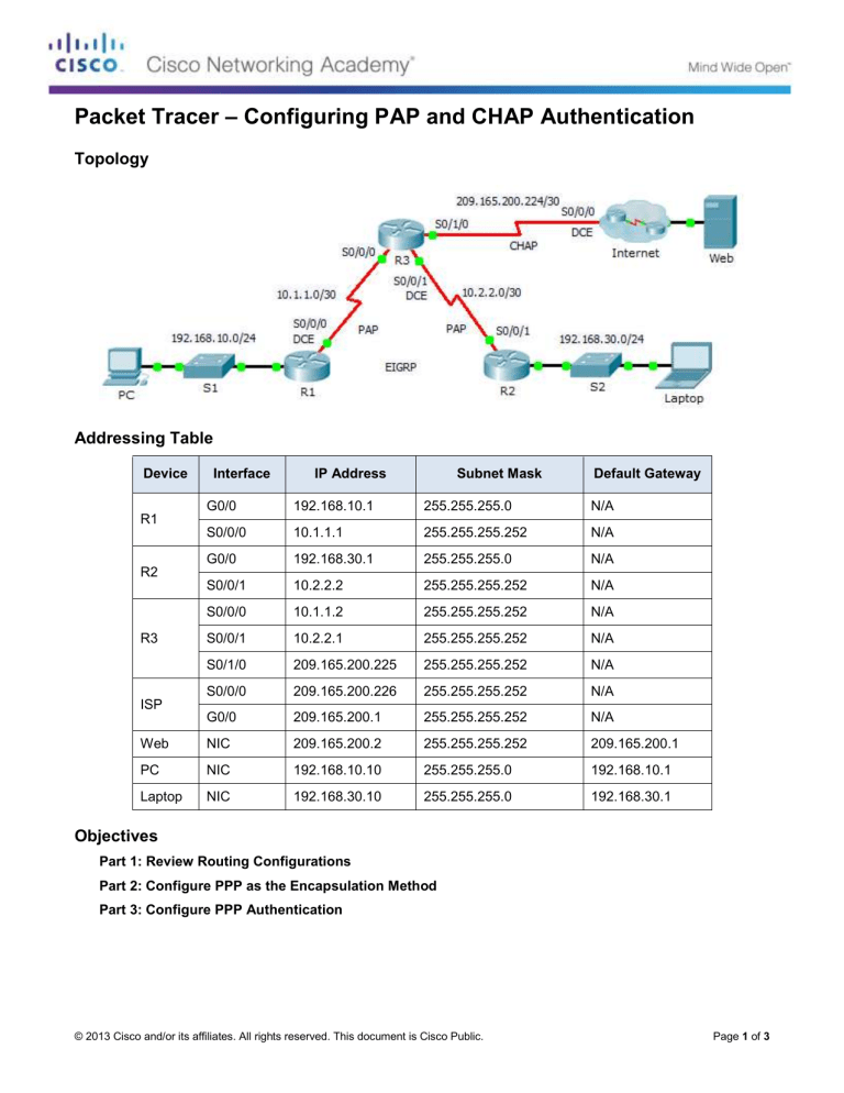
Packet Tracer – Configuring PAP and CHAP Authentication Topology Addressing Table Device Interface IP Address Subnet Mask Default Gateway G0/0 192.168.10.1 255.255.255.0 N/A S0/0/0 10.1.1.1 255.255.255.252 N/A G0/0 192.168.30.1 255.255.255.0 N/A S0/0/1 10.2.2.2 255.255.255.252 N/A S0/0/0 10.1.1.2 255.255.255.252 N/A S0/0/1 10.2.2.1 255.255.255.252 N/A S0/1/0 209.165.200.225 255.255.255.252 N/A S0/0/0 209.165.200.226 255.255.255.252 N/A G0/0 209.165.200.1 255.255.255.252 N/A Web NIC 209.165.200.2 255.255.255.252 209.165.200.1 PC NIC 192.168.10.10 255.255.255.0 192.168.10.1 Laptop NIC 192.168.30.10 255.255.255.0 192.168.30.1 R1 R2 R3 ISP Objectives Part 1: Review Routing Configurations Part 2: Configure PPP as the Encapsulation Method Part 3: Configure PPP Authentication © 2013 Cisco and/or its affiliates. All rights reserved. This document is Cisco Public. Page 1 of 3 Packet Tracer – Configuring PAP and CHAP Authentication Background In this activity, you will practice configuring PPP encapsulation on serial links. You will also configure PPP PAP authentication and PPP CHAP authentication. Part 1: Review Routing Configurations Step 1: View running configurations on all routers. While reviewing the router configurations, note the use of both static and dynamic routes in the topology. Step 2: Test connectivity between computers and the web server. From PC and Laptop, ping the web server at 209.165.200.2. Both ping commands should be successful. Remember to give enough time for STP and EIGRP to converge. Part 2: Configure PPP as the Encapsulation Method Step 1: Configure R1 to use PPP encapsulation with R3. Enter the following commands on R1: R1(config)# interface s0/0/0 R1(config-if)# encapsulation ppp Step 2: Configure R2 to use PPP encapsulation with R3. Enter the appropriate commands on R2: Step 3: Configure R3 to use PPP encapsulation with R1, R2, and ISP. Enter the appropriate commands on R3: Step 4: Configure ISP to use PPP encapsulation with R3. a. Click the Internet cloud, then ISP. Enter the following commands: Router(config)# interface s0/0/0 Router(config-if)# encapsulation ppp b. Exit the Internet cloud by clicking Back in the upper left corner or by pressing Alt+left arrow. Step 5: Test connectivity to the web server. PC and Laptop should be able to ping the web server at 209.165.200.2. This may take some time as interfaces start working again and EIGRP reconverges. Part 3: Configure PPP Authentication Step 1: Configure PPP PAP Authentication Between R1 and R3. Note: Instead of using the keyword password as shown in the curriculum, you will use the keyword secret to provide a better encryption of the password. a. Enter the following commands into R1: R1(config)# username R3 secret class © 2013 Cisco and/or its affiliates. All rights reserved. This document is Cisco Public. Page 2 of 3 Packet Tracer – Configuring PAP and CHAP Authentication R1(config)# interface s0/0/0 R1(config-if)# ppp authentication pap R1(config-if)# ppp pap sent-username R1 password cisco b. Enter the following commands into R3: R3(config)# username R1 secret cisco R3(config)# interface s0/0/0 R3(config-if)# ppp authentication pap R3(config-if)# ppp pap sent-username R3 password class Step 2: Configure PPP PAP Authentication Between R2 and R3. Repeat step 1 to configure authentication between R2 and R3 changing the usernames as needed. Note that each password sent on each serial port matches the password expected by the opposite router. Step 3: Configure PPP CHAP Authentication Between R3 and ISP. a. Enter the following commands into ISP. The hostname is sent as the username: Router(config)# hostname ISP ISP(config)# username R3 secret cisco ISP(config)# interface s0/0/0 ISP(config-if)# ppp authentication chap b. Enter the following commands into R3. The passwords must match for CHAP authentication: R3(config)# username ISP secret cisco R3(config)# interface serial0/1/0 R3(config-if)# ppp authentication chap Step 4: Test connectivity between computers and the web server. From PC and Laptop, ping the web server at 209.165.200.2. Both ping commands should be successful. Remember to give enough time for STP and EIGRP to converge. © 2013 Cisco and/or its affiliates. All rights reserved. This document is Cisco Public. Page 3 of 3
