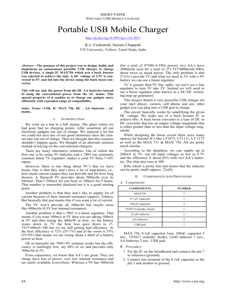
SHORT PAPER PORTABLE USB MOBILE CHARGER Portable USB Mobile Charger http://dx.doi.org/10.3991/ijes.v3i3.4937 K.L.Venkatesh, Sairam Chappidi VIT University, Vellore, Tamil Nadu, India Abstract—The purpose of this project was to design, build, and implement an autonomous portable USB charger to charge USB devices. A single IC MAX756 which acts a buck booster was selected to achieve the task. A DC voltage of 3.5V is converted to 5V and fed into the device using the buck boost converter. This will use only the power from the DC AA batteries instead of using the conventional power from the AC mains. This special property of it enables us to charge our gadgets more efficiently with expended range of compatibility. Index Terms—USB, IC MAX 756, DC , AA batteries , AC mains. I. INTRODUCTION We went on a trip to a hill station. The place where we had gone had no charging points. After sometime all our electronic gadgets ran out of charge. We enjoyed a lot but we could not save any of our good memories since the camera also ran out of charge. Then we thought that this scenario shouldn’t happen again. We thought of an alternate solution instead of relying on the conventional chargers. There are many alternative solutions. Out of which the first one is by using 9V batteries and a 7805 (an extremely common linear 5V regulator: makes a solid 5V from 7-18V input). However, there is one thing about 9V’s that we have learnt. One is that they don’t have a lot of amp-hours, i.e., how much current (amps) they can provide and for how long (hours). A Duracell 9V provides about 500mAh over its lifetime. That’s 500mA for one hour or 100mA for 5 hours. That number is somewhat idealized but it is a good starting point. Another problem is that they don’t like to supply lot of current because of their internal resistance (approx. 2ohms), But basically that just means that if you want a lot of current. The 9V won’t provide all 500mAh but maybe more like 400mAh (0.5V lost internal resistance). Another problem is that a 7805 is a linear regulator. That means if you want 100mA at 5V then you are taking 100mA at 9V and then losing the 400mW as heat. As the battery wears down to 7V the heat loss goes down to (75V)*100mA=2W but we are still getting bad efficiency. At the best efficiency is 72% (5V/7V) and at the worst is 55% (5V/9V) that means we are losing about a third of a battery power as heat. Ok so basically the 7805+9V solution works but the efficiency is startlingly low, say 60% or so, and provides only 300mAh at 5V. From experience, we know that AA’s are great. They are cheap, have lots of power, very low internal resistance and are easily available everywhere. Whereas a 9V has 500mAh 44 (for a total of 9*500=4.5Wh power) two AA’s have 3000mAh each for a total of 2*1.5V*3000mAh=9Wh, about twice as much power. The only problem is that 2*AA’s provide 3V and what we need is 5V with a 9V battery we can use a linear regulator 5V is greater than 9V but, sadly, we can’t use a line regulator to turn 3V into 5V. Instead we will need to use a boost regulator (also known as a DC/DC switching/step-up generator). This project details a very powerful USB charger for your mp3 player, camera, cell phone and any other gadget you can plug into a USB port to charge. The circuit basically works by amplifying the given DC voltage. We make use of a buck booster IC to achieve this. A buck boost converter is a type of DC to DC converter that has an output voltage magnitude that is either greater than or less than the input voltage magnitude. While designing the boost circuit there were many options for booster ICs like LT1073, LT1111, LT 1173 as well as the MAX 751 & MAX 756. All are pretty much similar. According to the datasheet, we can supply up to 200mA @ 5V, run off input voltages as low as 0.7V and the efficiency is about 85% with two AA’s batteries. The chip also runs at 500 KHz which is pretty fast and means that the inductor can be pretty small (approx. 22uH). II. COMPONENTS AND PROCEDURE A. Components: COMPONENTS NUMBER MAX756 1 0.1 !F capacitor 1 100 !F capacitor 2 1N5817(schottky diode) 1 22 !H inductor 1 AA batteries 2 USB jack 1 MAX 756, 0.1uF capacitor 1nos, 100uF, capacitor 2 nos., 1N5817 (schotky diode), 22uH inductor 1 nos., AA batteries 2 nos., USB jack. B. Procedure 1. Fix the IC on the breadboard and connect the pin 7 to reference (ground). 2. Connect one terminal of the 0.1uF capacitor to the pin 3 and another to ground. http://www.i-jes.org SHORT PAPER PORTABLE USB MOBILE CHARGER 3. Connect schottky diode to the pin 8 and connect pin6 to the other terminal of the diode. 4. Place one terminal of the capacitor of 100uF at above junction and other to the ground. 5. Give the input of 2V to pin 5 at the same junction place 100uF capacitor and connect other terminal to ground. 6. Place one terminal of 22uH inductor at the same junction and other terminal to the pin 8 before the diode. 7. We get the output at the junction of pin 8 and pin 6. st 8. This output is connected to the USB jack (1 and last pin). III. CONCLUSION We have achieved the USB portable charger using a buck booster IC MAX756. It has been used to convert a 3V to a 5V DC supply. We can use a lesser input voltage also but the charging span is high. The circuit developed for charging is very compact, efficient and can be moved from one place to another very easily. It is easy to handle. Using this as the basic we want to extend our project without satisfying with AA batteries. We want to make use of other forms of energy which will reduce the cost of the charger and make it compactable with all other sources. We want to make use of wind energy and piezo electric substances and create USB charger which receives its power from wind energy and stress… Figure 1. Operating Circuit REFERENCES [1] [2] Kaypmaz, T.C.; Tuncay, R.N.;, "An advanced cell model for diagnosing faults in operation of Li-ion Polymer batteries," Vehicle Power and Propulsion Conference (VPPC), 2011 IEEE, vol., no., pp.1-5, 6-9 Sept. 2011. Pastre, M.; Krummenacher, F.; Kazanc, O.; Pour, N.K.; Pace, C.; Rigert, S.; Kayal, M.;, "A solar battery charger with maximum power point tracking," Electronics, Circuits and Systems (ICECS), 2011 18th IEEE International Conference on, vol., no., pp.394-397, 11-14 Dec. 2011 http://dx.doi.org/10.1109/icecs.2011.6122296 AUTHORS K.L.Venkatesh and Sairam Chappidi are with VIT University, Vellore, Tamil Nadu, India. Submitted 06 August 2015. Published as resubmitted by the authors 10 October 2015. Figure 2. Pin Configuration MAX757 ! iJES ‒ Volume 3, Issue 3, 2015 45


