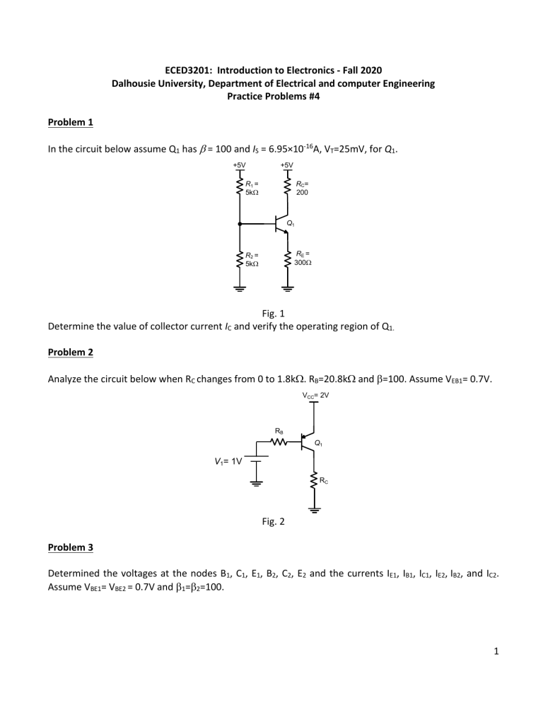
ECED3201: Introduction to Electronics - Fall 2020 Dalhousie University, Department of Electrical and computer Engineering Practice Problems #4 Problem 1 In the circuit below assume Q1 has = 100 and IS = 6.95×10⁻¹⁶A, VT=25mV, for Q1. +5V +5V RC= 200 R1 = 5kW Q1 RE = 300W R2 = 5kW Fig. 1 Determine the value of collector current IC and verify the operating region of Q1. Problem 2 Analyze the circuit below when RC changes from 0 to 1.8kW. RB=20.8kW and =100. Assume VEB1= 0.7V. VCC= 2V RB Q1 V1= 1V RC Fig. 2 Problem 3 Determined the voltages at the nodes B1, C1, E1, B2, C2, E2 and the currents IE1, IB1, IC1, IE2, IB2, and IC2. Assume VBE1= VBE2 = 0.7V and 1=2=100. 1 +6V +6V +6V RC1= 1.2kW RB1 = 3kW RC2 = 1kW C1 B1 C2 Q1 E1 B2 Q2 E2 RE1 = 1kW RB2 = 3kW RE2 = 2.5kW Fig. 3 Problem 4 In this circuit below, assume VEB1 = VBE2 = 0.7V, and 1=2=100. Determine the currents IE1, IB1, IC1, IE2, IB2, and IC2 and verify the region of operation of Q1 and Q2. +5V +5V 9.1kW 5.1kW Q1 Q2 100kW 9.1kW -5V 4.3kW -5V Problem 5 In the circuit shown below, the transistor has VEB=0.7V and =30. a) Find the values of VB, VE, and VC. b) If RB is raised to 270 kW, what voltages result? c) With RB = 270kW, what value of would return the voltages of the values first calculated? 2 +9V RE 2.7kW E B Q C RC RB 27kW 2.7kW -9V Fig. 5 3
