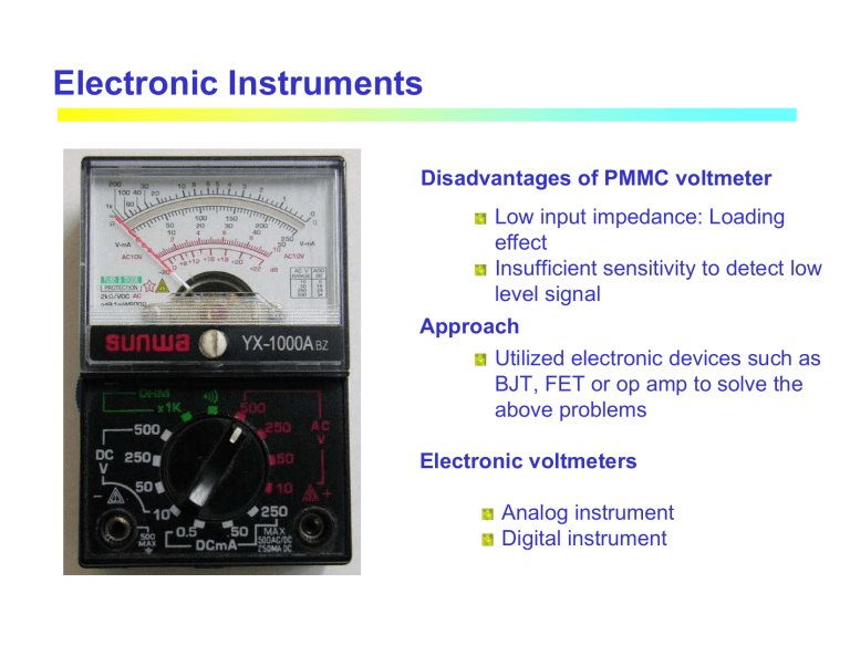
Electronic Instruments Disadvantages of PMMC voltmeter Low input impedance: Loading effect Insufficient sensitivity to detect low level signal Approach Utilized electronic devices such as BJT, FET or op amp to solve the above problems Electronic voltmeters Analog instrument Digital instrument Rm Voltmeter R1 EB Rs Basic PMMC Ammeter Ohmmeter D Rm AC voltmeter Electronic voltmeter RS Ammeter R1 R2 Electronic voltmeter Basic Electronic voltmeter Voltmeter EB R1 Ohmmeter D Electronic voltmeter AC voltmeter Electronic voltmeter Loading Effect R1 100kΩ 100kΩ 5V 6.7 V 10 V 10 V R2 100kΩ 5V 3.3 V V 100kΩ 100kΩ Vmeas = Circuit under measurement Circuit before measurement 100kΩ 100 // 100 10 V = 3.3 V 100 + 100 // 100 100kΩ 6V 5.2 V 10 V 10 V 100kΩ Vmeas = 4V 200 // 100 10 V = 4.0 V 100 + 200 // 100 V 100kΩ 200kΩ Vmeas = 4.8 V V 1000 // 100 10 V = 4.8 V 100 + 1000 // 100 1000kΩ Loading Effect Example Find the voltage reading and % error of each reading obtained with a voltmeter on (i) 5 V range, (ii) 10 V range and (iii) 30 V range, if the instrument has a 20 kΩ/V sensitivity, an accuracy 1% of full scale deflection and the meter is connected across Rb SOLUTION The voltage drop across Rb with output to the voltmeter connection Ra 45kΩ 50 V Rb 5kΩ V Rm Loading Effect Range (V) Vb . (V) Loading error (V) Meter error (V) Total error (V) % error 5 4.78 -0.22 ± 0.05 ± 0.27 ± 5.36 10 4.88 -0.12 ± 0.1 ± 0.22 ± 4.40 30 4.95 -0.05 ± 0.3 ± 0.35 ± 6.10 Transistor Voltmeter: Emitter Follower + Basic concept IB + Voltage to be Vin measured VBE Emitter follower Rs Vin reduce output resistance Voltage drop across meter: Vm = Vin − VBE where VBE is base-emitter voltage ~ 0.7 V for Si Meter current: Transistor base current: Vin − VBE Rs + Rm IE IB ≈ hFE - VCC Rm Ri = increase input resistance IE = Im Vin IB PMMC Schematic diagram of emitter follower Im = hFE = Transistor current gain (Typical values ~ 100-200 Transistor Voltmeter: Emitter Follower Circuit input resistance: Ri = Vin V ≈ hFE in ≈ hFE ( Rs + Rm ) IB IE Example The simple emitter-follower circuit has VCC = 20 V, Rs+Rm = 9.3 kΩ, Im = 1mA at full scale, and transistor hFE = 100 (a) Calculate the meter current when Vin = 10 V (b) Determine the voltmeter input resistance with and without the transistor. SOLUTION + IB + VBE IE = Im Rs Vin Rm Ri = - VCC Vin IB - Transistor Voltmeter: Emitter Follower *The base-emitter voltage drop (VBE) introduces some limitations in using emitter follower as a voltmeter: •The circuit cannot measure the input voltage less than 0.6 V •a non-proportional deflection: error From the above experiment, if we apply Vin with 5 V, the meter should read half of full scale I.e. Im = 0.5 mA. But, the simple calculation shows that Im = 0.46 mA Bridge configuration +VCC R4 Q1 V Q2 R5 VP Vin R2 VE1 Rs Rm I2 VE2 Vm = VE1 − VE 2 R3 I3 where R6 Zero adjust -VEE PMMC VE1 = Vin − VBE1 VE 2 = VP − VBE 2 Use negative supply also to measure Vin < 0.6 V Practical emitter-follower voltmeter using second transistor Q2 and voltage divider R4, R5 and R6 to eliminate VBE error in Q1 Transistor Voltmeter: Emitter Follower At the condition of Vin = 0, Vp should be set to give zero meter reading, Vm = 0. Therefore, the potentiometer R5 is for the zero adjust. If transistors Q1 and Q2 are identical, VBE1 = VBE2 Vm = VE1 − VE 2 = Vin − VBE1 − (V p − VBE 2 ) = Vin − V p At Vin = 0 -> Vm = 0, give Vp = 0 Consequently, if Vp is set properly, Vm will be the same as Vin Example An emitter-follower voltmeter circuit as shown in the previous picture has R2 = R3 = 3.9 kΩ and supply with ±12 V. Calculate the meter circuit voltage when Vin = 1 V and when Vin = 0.5 V. Assume, both transistors have VBE = 0.7 V SOLUTION when Vin = 1 V when Vin = 0.5 V Voltage Range Changing: Input Attenuator 800k Ra 5V Voltage to be measured 100k E 60k 1V Input The input attenuator accurately divides the voltage to Range Switch be measured before it is applied to the input transistor. Calculation shows that the input voltage Vin is always 1 V when the maximum input is applied on any range Rb 10V Rc 25V 40k Rd The measurement point always sees a constant input resistance of 1 MΩ Vin To meter Example On the 5 V range: Vin = 5 V × = 5 V× =1 V Rb + Rc + Rd Ra + Rb + Rc + Rd 100 kΩ + 60 kΩ + 40 kΩ 800 kΩ + 100 kΩ + 60 kΩ + 40 kΩ FET Input Voltmeter The addition of FET at the input gives higher input resistance than can be achieved with a bipolar transistor Input attenuator FET input stage Emitter follower +VCC 800k Ra 1V R4 5V 100k Rb 60k Rc E 10V 25V 40k Q1 EG VG S V Q2 R5 VP VS I2 R2 Rs+Rm R3 I3 Rd R6 -VEE PMMC A FET Input Voltmeter Vm = VE1 − VE 2 where VE1 = EG − VGS − VBE1 VE 2 = VP − VBE 2 In general, it is not simple to calculate VGS, for simplicity, we assume that VGS will be given. FET Input Voltmeter Example Determine the meter reading for the FET input voltmeter in the previous figure, when E = 7.5 V and the meter is set to its 10 V range. The FET gate-source voltage is –5 V, VP = 5 V, Rs+Rm = 1 kΩ and Im = 1 mA at full scale SOLUTION Input attenuator FET input stage Emitter follower +VCC 800k Ra 1V R4 5V 100k E 60k Rb 10V Rc 25V 40k Rd Q1 EG VG S V Q2 R5 VP VS I2 R2 Rs+Rm R3 I3 R6 -VEE On the 10 V range: Operational Amplifier Voltmeter Op-Amp Amplifier Voltmeter Non-inverting amplifier Vout = (1 + meter circuit +VCC The voltage gain + E - I4 Av = (1 + R4 -VEE IB R4 )E R3 I3 Vout Rs+Rm R4 ) R3 Selection of R3 and R4 R3 E R3 = I3 and R4 = Vout − E I3 The non-inverting amplifier gives a very high input impedance and very low output impedance. Therefore, the loading effect can be neglected. Furthermore, it can provide gain with enabling to measure low level input voltage. Operational Amplifier Voltmeter Example Design an op-amp Voltmeter circuit which can measure a maximum input of 20 mV. The op-amp input current is 0.2 µA, and the meter circuit has Im = 100 µA FSD and Rm = 10 kΩ. Determine suitable resistance values for R3 and R4 To neglect the effect of IB, the condition of I4 >> IB must be satisfied. The rule of thumb suggested I4 should be at least 100 times greater than IB Select I4 = 1000 x IB = 1000 x 0.2 µA = 0.2 mA meter SOLUTION Non-inverting amplifier circuit At full scale: Im = 100 µA +VCC + E - I4 R4 -VEE IB I3 R3 Vout Rs+Rm Operational Amplifier Voltmeter Op-Amp Amplifier Voltmeter: voltage to current converter Since I3 >> IB, therefore Im= I3 +VCC + EB - Meter current I m = I3 = Meter voltage Vm = Im -VEE Rs+Rm IB VR3 E R3 Rm E R3 if Rm > R3, voltage E is amplified by the ratio of Rm/R3 R3 I3 Current Measurement with Electronic Voltmeter Electronic voltmeter +VC C + - Rs+Rm -VEE E R3 + + RS - - I Ammeter terminals An electronic voltmeter can be used for current measurement by measuring the voltage drop across a shunt (Rs). The instrument scale is calibrated to indicate current. Electronic Ohmmeter: Series Connection range switch 1MΩ 100kΩ R1 A R1 1kΩ Rx = 0 100Ω EB 1.5V M s c ete al r f e u ll standard resistor 10Ω Rx E + Electronic Rx = ∞ voltmeter (1.5 V range) - Ohmmeter scale for electronic instrument B Series Ohmmeter for electronic instrument At Rx = ∞ or open circuit, the voltmeter indicate full scale defection (E = 1.5 V) and Rx = 0 or shorted circuit, since E = 0, no defection is observed. At other values of resistance, the battery voltage EB is potentially divided across R1 and Rx, given by E = EB Rx R1 + Rx Suppose that R1 is set to 1 kΩ 1 kΩ E = 1.5 V × = 0.75 V (50% defection) 1 kΩ + 1 kΩ Thus if Rx = R1, half scale will be indicated Electronic Ohmmeter: Series Connection Example For the electronic ohmmeter in the Figure, determine the resistance scale marking at 1/3 and 2/3 of full scale standard resistor E = EB SOLUTION From range switch 1MΩ Rearrange, give us 100kΩ A R1 1kΩ Rx = Rx R1 + Rx R1 EB E −1 100Ω EB 1.5V 10Ω + Rx E Electronic voltmeter (1.5 V range) - At 1/3 FSD; E = EB/3 Rx = R1/2 R1 2R1 Rx = 0 M s c ete al r f e u ll B Rx = ∞ R1 R = 1 EB × 3 −1 2 EB At 2/3 FSD; E = 2EB/3 Rx = R1 = 2 R1 EB × 3 −1 2 EB Electronic Ohmmeter: Parallel Connection At Rx = ∞ or open circuit, + R1 4kΩ E = EB A 6V R2 1.33kΩ - = 6 V× + Rx E R2 R1 + R2 Electronic voltmeter 1.33 kΩ = 1.5 V 4 kΩ + 1.33 kΩ (1.5 V range) - Therefore, this circuit give FSD, when Rx = ∞ B Shunt Ohmmeter for electronic instrument At any value of Rx E = EB When, Rx = 0 Ω, E = 0 V, therefore, the meter gives no defection. R2 || Rx R1 + R2 || Rx So, the meter indicates half-scale when Rx = R1|| R2 AC Electronic Voltmeter Principle Most ac measurements are made with ac-to-dc converter, which produce a dc current/voltage proportional to the ac input being measured Vin ac to dc converter dc meter Classification: Average responding periodic signal only Peak responding any signal RMS responding (True rms meter) AC Electronic Voltmeter The scale on ac voltmeters are ordinarily calibrated in rms volts Average responding meter Form factor is the ratio of the rms value to the average value of the wave form Vin ac to dc converter dc meter Vrms Form Factor = Vaverage It should be noted that the rms value is calculated from Vin, while the average value is calculated from the output of ac-dc converter. Peak responding meter Form factor is the ratio of the peak value to the rms value of the wave form Crest Factor = V peak Vrms Average-Responding Meter In this type of instrument, the ac signal is rectified and then fed to a dc millimeter. In the meter instrument, the rectified current is averaged either by a filter or by the ballistic characteristics of the meter to produce a steady deflection of the meter pointer. + E Input waveform +VD+ D1 Vout output waveform Vm Vout = E Vm = E − VD where VD = cut-in voltage ~0.6-0.7 for Si For the negative cycle, Vout = E Vm = 0 Since Diode D1 is revered bias, no current flow through meter E +VD- output waveform + D1 Input waveform - Conventional half-wave rectifier For the positive cycle, + - Vout Vm - precision rectifier For the positive cycle, Vout = Vm = E For the negative cycle, Vout = 0 Therefore, the voltage drop in the forward bias can be compensated by this configuration Average-Responding Meter V2 Vin V1 V2 V1 Vin Average-Responding Voltmeter Voltage to current converter precision rectifier precision rectifier +VCC C1 E + R1 + VF - - D1 +VCC C1 Rs+Rm -VEE meter current E Im + R1 D1 D3 Rs+Rm meter current -VEE D2 D4 R3 Full-wave rectifier Half-wave rectifier Meter peak current Ip = R3 Ep R3 Average meter current I = 1 I = 0.318I av p p π Meter peak current Ip = Average meter current I av = Ep R3 2 π I p = 0.637I p Average-Responding Voltmeter Example The half-wave rectifier electronic voltmeter circuit uses a meter with a FSD current of 1 mA. The meter a coil resistance is 1.2 kΩ. Calculate the value of R3 that will give meter full-scale pointer deflection when the ac input voltage is 100 mV (rms). Also determine the meter deflection when the input is 50 mV. SOLUTION at FSD, the average meter current is 1 mA precision rectifier +VCC C1 E R1 + + VF - - D1 Rs+Rm -VEE meter current R3 Peak-Responding Voltmeter The primary difference between the peak-responding voltmeter and the averageresponding voltmeter is the use of a storage capacitor with the rectifying diode. dc amplifier VD~0.7V Vin C + VC - Charge cycle R Vin C Discharge cycle R the input impedance of the dc amp In the first positive cycle: VC tracks Vin with the difference of VD, until Vin reaches its peak value. After this point, diode is reversed bias and the circuit keeps VC at Vp – VD. The effect of discharging through R will be minimized if its value is large enough to yield that RC >> T. Peak-Responding Voltmeter VC tracks Vin VC Vin RMS-Responding Voltmeter Suitable for: low duty-cycle pulse trains voltages of undetermined waveform T RMS value definition: Mathematic Vin x 2 Vrms 1 2 = v (t )dt T ∫0 Vout ∫ RMS value definition: Physical rms voltage is equivalent to a dc voltage which generates the same amount of heat power in a resistive load that the ac voltage does. Temp. rise ∝ Vrms Thermocouple I heating wire TC output (mV) Millivoltmeter Non-linear Difficult to calibrate scale Temp(oC) RMS-Responding Voltmeter Null-balance technique: non-linear cancellation Compare the heating power generated by input voltage to the heating power generated the dc amplifier Measuring thermocouple + ac input voltage ac Amplifier dc Amplifier - + Balancing thermocouple Vin Heater & TC + A Heater & TC Vout Feedback current Negative Feedback VT1 Vin Heater & TC Ve + - VT2 Vout A Heater & TC Vout = Ve = A (VT 1 − VT 2 ) Let, VT1 = k Vin and VT2 = k Vout where k is proportional constant of the heater and TC in the system. Note that k may depend on the level of the input signal Vout = A ( kVin − kVout ) Vout Ak = Vin 1 + Ak If A is large Vout ≈ Vin If the amplifier gain is very large, Vout is equal to Vin, this means that the dc voltage output is therefore equal to the effective, or rms value of the input voltage


