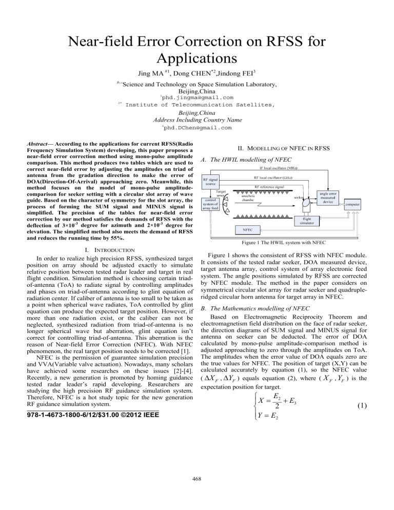
Near-field Error Correction on RFSS for Applications Jing MA #1, Dong CHEN*2,Jindong FEI3 #13 Science and Technology on Space Simulation Laboratory, Beijing,China 1 2* phd.jingma@gmail.com Institute of Telecommunication Satellites, Beijing,China Address Including Country Name 2 phd.DChen@gmail.com Abstract— According to the applications for current RFSS(Radio Frequency Simulation System) developing, this paper proposes a near-field error correction method using mono-pulse amplitude comparison. This method produces two tables which are used to correct near-field error by adjusting the amplitudes on triad of antenna from the gradation direction to make the error of DOA(Direction-Of-Arrival) approaching zero. Meanwhile, this method focuses on the model of mono-pulse amplitudecomparison for seeker setting with a circular slot array of wave guide. Based on the character of symmetry for the slot array, the process of forming the SUM signal and MINUS signal is simplified. The precision of the tables for near-field error correction by our method satisfies the demands of RFSS with the deflection of 3×10⁻³ degree for azimuth and 2×10⁻³ degree for elevation. The simplified method also meets the demand of RFSS and reduces the running time by 55%. I. INTRODUCTION In order to realize high precision RFSS, synthesized target position on array should be adjusted exactly to simulate relative position between tested radar leader and target in real flight condition. Simulation method is choosing certain triadof-antenna (ToA) to radiate signal by controlling amplitudes and phases on triad-of-antenna according to glint equation of radiation center. If caliber of antenna is too small to be taken as a point when spherical wave radiates, ToA controlled by glint equation can produce the expected target position. However, if more than one radiation exist, or the caliber can not be neglected, synthesized radiation from triad-of-antenna is no longer spherical wave but aberration, glint equation isn’t correct for controlling triad-of-antenna. This aberration is the reason of Near-field Error Correction (NFEC). With NFEC phenomenon, the real target position needs to be corrected [1]. NFEC is the permission of guarantee simulation precision and VVA(Variable valve actuation). Nowadays, many scholars have achieved some researches on these issues [2]-[4]. Recently, a new generation is promoted by homing guidance tested radar leader’s rapid developing. Researchers are studying the high precision RF guidance simulation system. Therefore, NFEC is a hot study topic for the new generation RF guidance simulation system. ______________________________________ 978-1-4673-1800-6/12/$31.00 ©2012 IEEE II. MODELLING OF NFEC IN RFSS A. The HWIL modelling of NFEC Figure 1 The HWIL system with NFEC Figure 1 shows the consistent of RFSS with NFEC module. It consists of the tested radar seeker, DOA measured device, target antenna array, control system of array electronic feed system. The angle positions simulated by RFSS are corrected by NFEC module. The method in the paper considers on symmetrical circular slot array for radar seeker and quadrupleridged circular horn antenna for target array in NFEC. B. The Mathematics modelling of NFEC Based on Electromagnetic Reciprocity Theorem and electromagnetism field distribution on the face of radar seeker, the direction diagrams of SUM signal and MINUS signal for antenna on seeker can be deducted. The error of DOA calculated by mono-pulse amplitude-comparison method is adjusted approaching to zero through the amplitudes on ToA. The amplitudes when the error value of DOA equals zero are the true values for NFEC. The position of target (X,Y) can be calculated accurately by equation (1), so the NFEC value ( 'X F , 'YF ) equals equation (2), where ( X F , YF ) is the expectation position for target. 468 E2 ­ E3 °X 2 ® °¯Y E2 (1) ­'X F X X F ® ¯'YF Y YF Every node in NFEC table obtained by the above method is saved into a form in computer, with ( X F , YF ) as the input and ( 'X F , 'YF ) as the result. If ( X F , YF ) is not a node in NFEC table, it is obtained by two dimensional linear interpolation. Therefore, the simulated target position is found in table as ­ X X F 'X F ® ¯Y YF 'YF (3) where, I ^ § ' (t ) · real ¨ ¸ cos(I ) © 6(t ) ¹ 0,7KH'2$DQGUHIHUHQFHVLJQDOLVVDPHGLUHFWLRQ S,7KH'2$DQGUHIHUHQFHVLJQDOLVRSSRVHGGLUHFWLRQ ' ¦ (6) in ³³ Sj f j ( x, z ) Fi. j ( x, y, z )dxdz (7) S j ( j 1, 2,3, 4) presents the jth area on the face ³³ Sj means getting the sum or integral of all cells S j . f j ( x, z ) is field distribution on seeker’s antenna. T is azimuth and \ is elevation. The direction diagrams of SUM signal, azimuth MINUS signal and elevation MINUS signal are SUM i Fi ,1 Fi ,2 Fi ,3 Fi ,4 DAZ i Fi ,1 Fi ,4 Fi ,2 Fi ,3 DELi Fi ,1 Fi ,2 Fi ,3 Fi ,4 (8) (9) (10) According to mono-pulse amplitude comparison method, DOA of azimuth and elevation are DT § DAZ1 E1 DAZ 2 E2 DAZ 3 E3 · real ¨ ¸ © SUM 1 E1 SUM 2 E2 SUM 3 E3 ¹ § DEL1 E1 DEL2 E2 DEL3 E3 · real ¨ ¸ © SUM 1 E1 SUM 2 E2 SUM 3 E3 ¹ (11) (12) (2) Mono-pulse Amplitude-comparison Method for Slot Array Antenna ' Figure 3 Mono-pulse Amplitude-comparison Method for Slot Array Antenna Figure 2 SUM signal and MINUS signal According to Electromagnetic Reciprocity Theorem, the field strength of ToA on the ith cell to jth cell is Fi , j ( x, y, z ) where, D\ means getting real part. e jkRi u u Mi u n 4S Ri Fi , j (\ , T ) ˄4˅ , real() A where, A is a constant, Mi is the inspired field of ith cell. u is unit vector from source field to inspired field. n is unit vector of direction on the face of the horn. Therefore, synthesized field on one quadrant of seeker is of antenna. C. Mono-pulse Amplitude-comparison method (1) Application of Mono-pulse Amplitude Comparison Method in the Detection of Radar Seeker One angle plane contents two overlapped beams receiving at same time, which are processed into SUM signal() and MINUS signal(Ƹ). MINUS signal is the DOA signal in this angle plane as Figure 2 shown. Mono-pulse amplitude comparison method compares two beams with same phase but different direction to obtain target position. When target leaves the center of the beam, the magnitude and polarity sign of receiving normalized MINUS signal(Ƹ/) present the position which the target locates. DOA is H Fi (2) Fi f j (5) f j is the field strength of cell x, y, z on seeker to the jth cell on triad of antenna; Fi is the field strength of the ith cell on ToA to the cell In RFSS, seeker’s antenna adopts symmetrical circular slot array, which contents four subarrays marked 1,2,3 and 4 as Figure 3 shown. Construct coordinates for slot array antenna, subarrays locate in four quadrants respectively. Then, DOAs of azimuth and elevation can be obtained by equation (11) and (12). When SUM signal and MINUS signal are generated on the face of seeker’s antenna, the direction diagrams are SUM (\ ,T ) GSUM (\ Ri , T Ri ) Eslot (rRi ,T Ri ,\ Ri ) (13) DAZ (\ ,T ) GDAZ (\ Ri ,T Ri ) Eslot (rRi , T Ri ,\ Ri ) x, y, z on seeker. It presents as 469 (14) DEL(\ ,T ) GDEL (\ Ri ,T Ri ) Eslot (rRi ,T Ri ,\ Ri ) (15) where, ( rR , T R ,\ R ) is the coordinate of the ith cell of ToA relative to seeker’s antenna; GSUM (\ Ri ,T Ri ) ǃ GDAZ (\ Ri ,T Ri ) ǃ GDEL (\ Ri ,T Ri ) are cell genes for SUM signal, azimuth MINUS signal and elevation MINUS signal of seeker’s antenna respectively. A slot on seeker’s antenna is presented by Eslot (rRi ,T Ri ,\ Ri ) ,which expresses as i i i AR to present this amplitude. Equation(17) can be simplified to g Sj1,k (a, b) g Sj2,k (a, b) g Sj3, k (a, b) g Sj4, k (a, b) 4 AR ¦ e j ( al R blR ) l 1 4 AR ¦ cos(alR blR ) j sin(alR blR ) §S · cos ¨ sin T Ri cos\ Ri ¸ V ©2 ¹ j m i 2 i 2 S 1 sin T R cos \ R Eslot (rRi ,T Ri ,\ Ri ) Build coordinates on the face of slot array antenna, cells on j ,k the same radius possess the same amplitude ASi , so make l 1 (23) Equation (23) is expanded by trigonometric function R R R R R R R R satisfying a1 a2 a3 a4 and b1 b4 b2 b3 . The cell gene is simplified to be calculated in a subarray avoiding complex operation, which is i & & e jkRR (sin\ e cos T Ri cos\ Ri e\ ) i RR i R T 3 n m ¦¦¦ (16) (24) GSUM (\ Ri , T Ri ) ASji, k cos(a ) cos(b) If each subarray on slot array antenna contents n u m cells, i 1 j 1 k 1 cell genes of SUM signal, azimuth MINUS signal and Similarly, the cell gene of azimuth MINUS signal and elevation MINUS signal can be decomposed to each slot, elevation MINUS signal are modeling as 3 n m GSUM (\Ri ,TRi ) 3 n m ¦¦¦ g j ,k S1 i 1 j 1 k 1 GDAZ (\ Ri , T Ri ) (a,b) gSj,k (a,b) gSj,k (a,b) gSj,k (a,b) 2 3 i 1 j 1 k 1 4 (17) GDAZ (\ ,T ) i R i R 3 n m ¦¦¦ g j ,k S1 i 1 j 1 k 1 j,k S2 j,k S3 GDEL (\Ri ,TRi ) n m ¦¦¦ g i1 j 1 k1 j,k S1 (a,b) gSj,k (a,b) gSj,k (a,b) gSj,k (a,b) 2 3 4 (19) j ,k where, g Si ( a, b) is cell gene for the cell on ith row and kth column in subarray ASji,k e j ( a b ) n m ¦¦¦ A j ,k Si cos(a ) sin(b) (25) sin(a ) cos(b) (26) D. Precision Target Position adjusting by Gradient method in NFEC E2 Si , presenting as g Sji,k (a, b) 3 j ,k Si Compared with equation (17),(18) and (19), operations of SUM and MINUS signals are simplified to deal with slots in only one subarray with avoiding complex operation, overlapped multiplications and additions. (18) 3 GDEL (\ Ri , T Ri ) i 1 j 1 k 1 (a,b) g (a,b) g (a,b) g (a,b) j ,k S4 ¦¦¦ A (20) ASji, k is radiation amplitude of this cell. E1 a and b are phase difference on X direction and Y direction in this cell’s coordinate respectively, presenting as a Z sin(T ) cos(\ )[( j 1)dx x0 ] (21) b Z sin(T ) cos(\ )[(k 1)dy y0 ] (22) \ and T are azimuth and elevation; dx and dy are spaces between each slot cell on X and Y direction. x0 is distance from origin to closest cell on X direction, so as y0 . Making use of symmetry relation in slot array antenna between four sunarray, equation (17),(18) and (19) about SUM signal, azimuth MINUS signal and elevation MINUS signal can be simplified in order to minimize the complexity of NFEC’s arithmetic and improve running time. E3 Figure 4 Control method for target in RFSS The RFSS with target array adopts electron control unit to realize the angle simulation of target movement. The target position can be controlled exactly through adjusting the signals, attenuator of amplitude and transposer for phase, on the ToA as Figure 4 shown. Reference [4] used Newton iterative algorithm to solve linear equations, equation (11) and equation (12) equaling to zero. However, because Newton iterative algorithm has slow convergence speed, this paper abandons linear equation solvent but adopts adjusting amplitudes of ToA on the gradient directions of azimuth and elevation to make the error of DOA calculated by mono-pulse amplitude comparison method approaching to zero, Gradient method in NFEC namely. Convergence speed of the Gradient method precedes which of Newton iterative algorithm. 470 Therefore, take the gradient direction of azimuth and elevation on amplitudes of ToA Ei , operation such as overlapped multiplications and additions, as well as improving running time. Table III enumerates precision and improvement for this simplification. 3 wD From overall, the precision of simplification can be \ G Ei grad ( Ei ) (27) guaranteed by 4×10⁻⁴ difference on azimuth and difference on u G Ei i 1 wEi 5×10⁻⁴ elevation. Nevertheless, the running time is improved to Appending the condition E1 E2 E3 1 , Ei is adjusted 55% on average. TABEL III iteratively to make DOA of azimuth and elevation approaching Precision and Improvement for Simplification to zero. When the precision is satisfied, the controlled Normalized DOA of azimuth DOA of elevation Running Amplitudes Time(ms) amplitudes on ToA are obtained by iteration end. The position on triad-ofTRUTH SIMPLIF TRUTH SIMPLIF TRUT SIMPL corrected by NFEC algorithm can be taken by equation (28). antenna ¦ ­ °\ ® °¯T E2 E3 2 E2 (28) III. THE RESULT OF NEAR-FIELD ERROR CORRECTION ON RFSS A. The table of near-field error correction Tables are needed to calculated for NFEC. According to above-mentioned method, two tables are obtained for azimuth and elevation. A triad of antenna can be divided into two symmetrical right angles. Therefore, the tables are formed for half data. The tables of azimuth and elevation are shown in Table I and Table II separately. TABLE I NFEC FOR AZIMUTH XF YF 0 0.1 0.3 0.5 0.7 0.9 'X 0.05 0.15 0.25 0.35 0.45 0 0.0128 0.0154 0.0256 0.0273 0.0166 0.026 0.027 0.0199 0 0.0186 0.0191 0.0149 0.0036 -0.017 0.0066 0.0067 0.0054 0.0017 -0.005 -0.0159 [1] [2] 0 0.1 0.3 0.5 0.7 0.9 0.05 0.15 0.25 0.35 0.45 0 0 0.0239 0 0.0157 0.0257 0 0.01 0.0096 0 0 0.0065 0 0.0171 0.0254 0 0.0048 -0.0052 -0.0255 0.25 0.3 0.35 0.4 0.45 0.0082 0.0118 0.0147 0.0102 0.0157 Y 0.0086 0.0120 0.0143 0.0109 0.0152 0.0209 0.0192 0.0120 0.0071 0.0201 Y 0.0201 0.0195 0.0114 0.0074 0.0206 H 45 43 42 42 41 IFY 17 20 21 19 20 REFERENCES 'Y 0 0.75 0.7 0.65 0.6 0.55 IV. CONCLUSION According to the applications for current RFSS developing, this paper proposes a near-field error correction method using mono-pulse amplitude-comparison. This method produces two tables of near-field error correction by adjusting the amplitudes on ToA on the gradation direction to make the error of DOA(Direction-Of-Arrival) which is measured by mono-pulse amplitude comparison method approaching zero. Meanwhile, this method focuses on the model of mono-pulse amplitude comparison for seeker setting a circular slot array of wave guide. Based on the character of symmetry for the slot array, the process of forming the SUM signal and MINUS signal is simplified. The precision of proposed method in this paper can satisfy the required application of RFSS, as reducing the running time. 0 TABLE II III NFEC FOR ELEVATION XF YF 0 0 0 0 0 [3] [4] -0.0386 [5] -0.0237 [6] B. Simplification accuracy of mono-pulse amplitude comparison for circular slot array antenna Mono-pulse amplitude comparison method for slot array antenna is introduced in Section II.C, where contains the simplification for SUM and MINUS signal, avoiding complex [7] [8] 471 CHEN Xun-da, The Dual Near-Field Effect in Radio Frequency Simulateion, JOURNAL OF SYSTEM SIMULATION, Volume 13 Number 1, January 2001. McPherson D.A., Near Field Angle Error Compensation for High Precision HWIL RF Missile Seeker Simulation[A], Proceeding of the 1993 SCSC[A], 1993, pp:640-645. Bishop C.B., Error Analysis of Point Targets in HWIL Simulation[A], Proceeding of the 1994 SCSC[C],1994, pp:373-378. Qingping JIANG, Simulation Techniques Reasearch on active and passive Broadband radio frequency, Thesis of Northwest Industry University, 2006. The reseach of simulation techniques in the experimentation and authentification in American Army, Report of Liu Tianshu, Congjun JIN. Verifying method of near-field error compensation of RFSS[C], Proc. of the 3rd China Guidance Navigation and Control Conference,2010. Liu Tianshu, Congjun JIN. Verifying method of array target simulation based on monopulse angle measurement[C], Proc. Of the Simulation Symposium, 2001:257-261. Robert S.Elliott, Antenna and design[B], Prentic-Hall. Inc., 1981.


