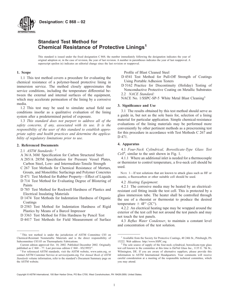
标准分享网 www.bzfxw.com 免费下载 The standard is downloaded from www.bzfxw.com Designation: C 868 – 02 Standard Test Method for Chemical Resistance of Protective Linings1 This standard is issued under the fixed designation C 868; the number immediately following the designation indicates the year of original adoption or, in the case of revision, the year of last revision. A number in parentheses indicates the year of last reapproval. A superscript epsilon (e) indicates an editorial change since the last revision or reapproval. Profile of Blast Cleaned Steel D 4541 Test Method for Pull-Off Strength of Coatings Using Portable Adhesion Testers D 5162 Practice for Discontinuity (Holiday) Testing of Nonconductive Protective Coating on Metallic Substrates 2.2 NACE Standard: NACE No. 1/SSPC-SP-5 White Metal Blast Cleaning3 1. Scope 1.1 This test method covers a procedure for evaluating the chemical resistance of a polymer-based protective lining in immersion service. The method closely approximates the service conditions, including the temperature differential between the external and internal surfaces of the equipment, which may accelerate permeation of the lining by a corrosive media. 1.2 This test may be used to simulate actual field use conditions insofar as a qualitative evaluation of the lining system after a predetermined period of exposure. 1.3 This standard does not purport to address all of the safety concerns, if any, associated with its use. It is the responsibility of the user of this standard to establish appropriate safety and health practices and determine the applicability of regulatory limitations prior to use. 3. Significance and Use 3.1 The results obtained by this test method should serve as a guide in, but not as the sole basis for, selection of a lining material for particular application. Simple chemical-resistance evaluations of the lining materials may be performed more conveniently by other pertinent methods as a prescreening test for this procedure in accordance with Test Methods C 267 and D 471. 4. Apparatus 4.1 Four-Neck Cylindrical, Borosilicate-Type Glass Test Cell4, similar to the unit shown in Fig. 1. 4.1.1 Where an additional inlet is needed for a thermocouple or thermistor to control temperature, a five-neck cell should be used. 2. Referenced Documents 2.1 ASTM Standards: 2 A 36/A 36M Specification for Carbon Structural Steel A 285/A 285M Specification for Pressure Vessel Plates, Carbon Steel, Low- and Intermediate-Tensile Strength C 267 Test Methods for Chemical Resistance of Mortars, Grouts, and Monolithic Surfacings and Polymer Concretes D 471 Test Method for Rubber Property—Effect of Liquids D 714 Test Method for Evaluating Degree of Blistering of Paints D 785 Test Method for Rockwell Hardness of Plastics and Electrical Insulating Materials D 1474 Test Methods for Indentation Hardness of Organic Coatings D 2583 Test Method for Indentation Hardness of Rigid Plastics by Means of a Barcol Impressor D 3363 Test Method for Film Hardness by Pencil Test D 4417 Test Methods for Field Measurement of Surface NOTE 1—If test solutions that are known to attack glass such as HF or caustic, a fluorocarbon or other suitable cell should be used. 4.2 Heating Equipment: 4.2.1 The corrosive media may be heated by an electricalresistant coil fitting inside the test cell. This is protected by a glass immersion tube. The heater shall be controlled through the use of a rheostat or thermostat to produce the desired temperature 6 4F° (2C°). 4.2.2 An electrical heating tape may be wrapped around the exterior of the test cell but not around the test panels and may not touch the test panels. 4.3 Reflux Water Condenser, to maintain a constant level and concentration of the test solution. 1 This test method is under the jurisdiction of ASTM Committee C03 on Chemical-Resistant Nonmetallic Materials and is the direct responsibility of Subcommittee C03.03 on Thermoplastic Fabrications. Current edition approved Oct. 10, 2002. Published December 2002. Originally published as C 868 – 77. Last previous edition C 868 – 85(1995)e1. 2 For referenced ASTM standards, visit the ASTM website, www.astm.org, or contact ASTM Customer Service at service@astm.org. For Annual Book of ASTM Standards volume information, refer to the standard’s Document Summary page on the ASTM website. 3 Available from the Society for Protective Coatings, 40 24th St., Pittsburgh, PA 15222. Web address: http://www.SSPC.org 4 The sole source of supply of the four-neck cylindrical, borosilicate-type glass test cell known to the committee at this time is DelVal Glass Inc., 1135 E. 7th St., Wilmington, DE. If you are aware of alternative suppliers, please provide this information to ASTM International Headquarters. Your comments will receive careful consideration at a meeting of the responsible technical committee, which you may attend. Copyright © ASTM International, 100 Barr Harbor Drive, PO Box C700, West Conshohocken, PA 19428-2959, United States. 1 标准搜搜网 www.bzsoso.com 提供各类标准行业资料免费下载 标准分享网 www.bzfxw.com 免费下载 The standard is downloaded from www.bzfxw.com C 868 – 02 FIG. 1 Four-Neck Cylindrical, Borosilicate-Type Glass Test Cell and Accessories 4.7.2 “C” clamp fixtures or stainless steel band clamps or other suitable means can be used to mount the test panels to the test cell. 4.7.3 Use clamping pressures sufficient to seal the opening, but not so great as to destroy the test cell or test panel or damage the test lining. 4.8 Cell Test Area: 4.8.1 The cells should be maintained in an open, well ventilated area with temperature controlled to 73 6 4F° (23 6 2C°). 4.8.2 The preferred method to ensure the free movement of air past the surfaces is to utilize grills or grating to support the cells with several inches of clearance beneath the grating to allow air flow past the plate surfaces. If this type of support is employed, cells should be at least 6 in. (152 mm) away from one another or any heat source. 4.8.3 If open grating support is not used, cells should be at least 12 in. (305 mm) from one another or from any potential source of heat. They should be placed on an open shelf or bench top in such a way that free convective cooling of the unlined side of the test panels may occur. 4.4 Gaskets, of a chemically resistant material, capable of withstanding the chemical environment. The gaskets shall also provide a tight seal between the test cell and test specimen. Gaskets having a Shore “A” Durometer of 60 are generally adequate. The gasket material shall be selected so that it does not contaminate the test solution. 4.5 Air or Gas Bubbler—It may be necessary to include an air or gas bubbler to agitate or aerate the solution. Where aeration is not required, a magnetic stirrer may be used to create agitation. 4.5.1 At solution temperatures below boiling, agitation is required to maintain temperature uniformity. Where the service solution is considered to be aerated, air should be bubbled into the solution. In cases where the solution will be air or oxygen depleted, nitrogen or other suitable inert gas should be used for agitation. 4.5.2 Insert a bubbler for air or other gas through the utility opening in the test cell. The bubbler shall consist of a piece of fluorocarbon or glass tubing 1⁄8 in. (3 mm) in inside diameter, attached to the ground-glass fitting in the utility opening, and extending almost to the bottom of the test cell. 4.6 Thermometer or Thermocouple, to fit the prescribed thermowell, capable of registering the temperature specified for the test. 4.7 Mounting Equipment (Alternatives): 4.7.1 Mount the test panels on the test cell with a minimum of three carbon steel bolts, 1⁄4 or 3⁄8 in. (6 or 9 mm) in diameter, using wing nuts for easy removal. 5. Test Specimens 5.1 Substrate: 5.1.1 Panels shall be commercial quality, unused, hot-rolled carbon steel (Specifications A 36/A 36M or A 285/A 285M) 1⁄4 by 8 by 8 in. (6 by 200 by 200 mm). 2 标准搜搜网 www.bzsoso.com 提供各类标准行业资料免费下载 标准分享网 www.bzfxw.com 免费下载 The standard is downloaded from www.bzfxw.com C 868 – 02 6.1.2 If no concentration is specified, it is understood that the chemical is used in its undiluted form. 6.2 Analysis of the test solution may be performed when the following conditions occur: 6.2.1 Loss of media or buildup of contaminants. 6.2.2 Any change of the test solution. NOTE 2—With appropriate modification and procedures, this method can be used to evaluate linings on other metallic substrates such as stainless steel or other alloys, copper, aluminum, etc., and to evaluate linings on concrete, fiber reinforced plastic (FRP), or other substrates. 5.2 Prepare one side of the panels according to the surface conditions of NACE No. 1 SSPC-SP-5. The profile depth of the cleaned steel shall be as recommended by the lining manufacturer. The average profile depth shall be measured by Test Methods D 4417. 5.3 Apply the lining to the test panels as prescribed by the manufacturer and in a manner as closely simulating field application as possible. For example, if the lining is to be spray applied in the field, the lining for the test panels should be spray applied also. Lining thickness should be within 10 % of the nominal thickness specified. 5.3.1 The opposite (unprepared) side should be left unlined. A very thin (1 to 3 mils, 25 to 76 µm) coating may be applied to the unprepared side, if necessary, to prevent rusting. 5.3.2 Wherever possible, duplicate test panels should be run to determine reproducibility of results. 5.4 Conditioning of Test Panels—Condition test panels for a period of 7 days at 73 6 4F° (23 6 2C°). Additional conditioning of test panels, including longer cure times or elevated cure temperatures, may be conducted if specified by the lining manufacturer. 5.5 Specimen Measurements: 5.5.1 Check the thickness of the lining material by using an appropriate dry-film thickness gage. 5.5.2 Check the discontinuities in the lining material of one-side exposure test panels by using Practice D 5162. Consult the lining manufacturer for the recommended voltage to be used. Low voltage detectors are not recommended unless specifically recommended by the lining manufacturer. 5.5.2.1 High-voltage holiday detection should not be used on linings that have been exposed. The test could be destructive and may not be meaningful since the dielectric strength of the lining material may be changed by the exposure. 5.5.2.2 If discontinuities are found, either repair the lining or replace the test panel(s). 7. Procedure 7.1 Following the conditioning period, clamp the test panels in place at the ends of the test cell with the lining material positioned against the cell interior. Use a suitable gasket material between the lining and cell faces described in 4.4 to ensure against leakage of the test solution. 7.2 The assembled test cell may be filled with tap water and held approximately 1 h to check for complete sealing of the apparatus. 7.3 Fill the test cell 2⁄3 to 3⁄4 of its total height with the test solution and commence heating, if required. Mark the outer, unexposed panel area, indicating the test solution level for visual control of the test solution level. 7.4 Disassemble the test cell at one month or other intervals for inspection. When the apparatus is reassembled, recharge it with fresh test media. Recharging of the test media may be necessary at more frequent intervals, if required due to the nature of the media, for instance, NaOCl (see Section 6). 7.4.1 When test panels are disassembled from the test cell, rinse the panels with distilled water and wipe dry. No other conditioning is required. 7.5 Interim Evaluation: 7.5.1 Make the visual inspection and record the results for the following: 7.5.1.1 Color—State any changes noted in the color of the lining. 7.5.1.2 Surface Gloss—Report any dulling of the lining surface. 7.5.1.3 Surface Texture—Note signs of chemical or physical erosion. 7.5.1.4 Blisters—Inspect the surface for blisters by visual and audible methods such as lightly tapping or applying a straight edge to the surface of the panel. Describe the size, quantity, and location of blisters. Use Test Method D 714 where possible. 7.5.1.5 Changes in the test solution. 7.6 Final Evaluation: 7.6.1 After the sixth month of exposure or upon failure, repeat the procedures described in Section 7.5 and conduct the following additional tests: 7.6.1.1 Determine the hardness of the lining as described in 5.5.4 on portions of the panel exposed to: (1) liquid solution, (2) vapor phase, (3) liquid-vapor interface, and (4) unexposed area. 7.6.1.2 Make an appraisal of the adhesion of the lining to the substrate. Depending on the type of lining, this appraisal may be made using different methods such as strip peeling, elcometer test (Test Method D 4541) or prying with a knife or similar equipment. Not all of these methods will provide a specific value. During this destructive evaluation, the location of blisters should be determined. The blisters may be at the NOTE 3—Certain linings are conductive and cannot be tested in this manner. 5.5.3 Visually inspect the lining surface of all panels before the test exposure is begun to determine the color, clarity, surface gloss, and surface texture; also, any gross imperfections such as voids, cracks, runs, or sags. 5.5.4 Determine the hardness of the lining by a suitable standard hardness test such as Test Methods D 785, D 1474, D 2583, and D 3363 in an area of the panel that will not be exposed to the test solution. Hardness determinations may be invalid for some aggregate-filled systems. 6. Test Solution 6.1 The test media shall simulate the anticipated service environment when testing lining materials for a specific application. 6.1.1 The concentration(s) of the chemical(s) shall be specified. Unless otherwise stated, all dilutions shall be made with distilled, demineralized or deionized water. 3 标准搜搜网 www.bzsoso.com 提供各类标准行业资料免费下载 标准分享网 www.bzfxw.com 免费下载 The standard is downloaded from www.bzfxw.com C 868 – 02 surface of the substrate, between layers within the lining system, or within one layer of the lining system. 7.6.1.3 High-voltage holiday detection should not be used on linings that have been exposed. The test could be destructive and may not be meaningful since the dielectric strength of the lining material may be changed by the exposure. tion, noting any changes in the surface texture, evidence of cracking, blistering, or delamination. Changes in media appearance should be reported. 8.3 Qualitative evaluation of the final inspection shall include an appraisal of adhesion of adhesion of the lining to the substrate, notation of any signs of substrate attack or corrosion such as metal rusting, metal darkening, or any visible oxides. 8.3.1 A pictorial study of test panels may also be kept. Pictures should be taken before exposure and at each test interval. Two sets of pictures should be taken at test conclusion: one set before destruction and one set after destruction. 8.3.2 When a degree of chemical attack is questionable, a microscopic examination may be of value. This is purely a qualitative examination to determine depth of degradation or possible degree of permeation of the lining by the test solution. 8. Report 8.1 The report shall include the following information concerning the lining system and test conditions: 8.1.1 Manufacturer’s name, product designation, and generic type; 8.1.2 Type of test substrate; 8.1.3 Method of panel preparation, including the depth of profile and all steps and application procedures used in the application of the lining. The initial thickness of the lining shall be measured and recorded; 8.1.4 Conditioning procedure; 8.1.5 Hardness, visual observations, and note any repairs or any discontinuities. The test method used to determine the hardness shall be noted; 8.1.6 Description of lining appearance prior to testing; and 8.1.7 Test conditions including test media, temperature, time of exposure, length of intervals between exposures, and frequency of recharging test solutions. 8.2 The results of each interim inspection shall comprise a description of the appearance of the test panel at each inspec- 9. Precision and Bias 9.1 This test method is as specific as possible in establishing reproducible methods and procedures. Final test result and report, however, depends heavily on visual observations and subjective evaluation and results and conclusions may vary. 9.2 Wherever possible, duplicate test panels should be run to determine reproducibility of results. 10. Keywords 10.1 blistering; cell test; corrosive media; discontinuities; holiday; permeation; profile depth; protective lining; chemical resistance; adhesion; coating ASTM International takes no position respecting the validity of any patent rights asserted in connection with any item mentioned in this standard. Users of this standard are expressly advised that determination of the validity of any such patent rights, and the risk of infringement of such rights, are entirely their own responsibility. This standard is subject to revision at any time by the responsible technical committee and must be reviewed every five years and if not revised, either reapproved or withdrawn. Your comments are invited either for revision of this standard or for additional standards and should be addressed to ASTM International Headquarters. Your comments will receive careful consideration at a meeting of the responsible technical committee, which you may attend. If you feel that your comments have not received a fair hearing you should make your views known to the ASTM Committee on Standards, at the address shown below. This standard is copyrighted by ASTM International, 100 Barr Harbor Drive, PO Box C700, West Conshohocken, PA 19428-2959, United States. Individual reprints (single or multiple copies) of this standard may be obtained by contacting ASTM at the above address or at 610-832-9585 (phone), 610-832-9555 (fax), or service@astm.org (e-mail); or through the ASTM website (www.astm.org). 4 标准搜搜网 www.bzsoso.com 提供各类标准行业资料免费下载


