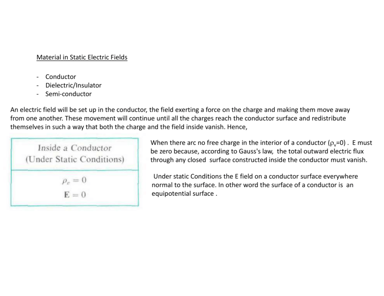
Material in Static Electric Fields - Conductor - Dielectric/Insulator - Semi-conductor An electric field will be set up in the conductor, the field exerting a force on the charge and making them move away from one another. These movement will continue until all the charges reach the conductor surface and redistribute themselves in such a way that both the charge and the field inside vanish. Hence, When there arc no free charge in the interior of a conductor (v=0) . E must be zero because, according to Gauss's law, the total outward electric flux through any closed surface constructed inside the conductor must vanish. Under static Conditions the E field on a conductor surface everywhere normal to the surface. In other word the surface of a conductor is an equipotential surface . Boundary condition Air-Conductor interface If h 0 and noting that E inside a conductor is zero. we obtain E1=E1t+E1n E2=E2t+E2n E1tW=0 The tangential component of the E field on a conductor surface is zero under static condition To find En the normal component of E at the surface of the conductor, we construct a Gaussian surface in the form of a thin pillbox with the top face in free pace and the bottom face in the conductor where E= 0. E1n=s/0 The normal component of the E field at a conductor-free space boundary is equal to the surface charge density on the conductor divided by the permittivity of free space. Dielectric in static Electric Field All material media are composed of atoms with a positively charged nucleus surrounded by negatively charged electrons. Although the molecules of dielectrics are macroscopically neutral, the presence of an external electric field causes a force to be exerted on each charged particle and results in small displacements of positive and negative charge in opposite directions. These are bound charges. The displacements, though small in comparison to atomic dimensions, nevertheless polarize a dielectric material and create electric dipoles. Induced electric dipoles will modify the electric field both inside and outside the dielectric material. The molecules of some dielectrics possess permanent dipole moments, even in the absence of an external polarizing field. Such molecules usually consist of two or more dissimilar atoms and are called polar molecules, in contrast to nonpolar molecules. To analyze the macroscopic effect of induced dipoles we define a polarization vector P which is the volume dipole moment density as where n is the number of molecules per unit volume and the numerator represents the vector sum of the induced dipole moments contained in a very small volume v. The dipole moment dp of an elemental volume dv' is dp = P dv', which produces an electrostatic potential lntegrating over the volume V' of the dielectric, we obtain the potential due to the polarized dielectric. where R is the distance from the elemental volume dv' to a fixed field point. Equivalent polarization surface charge density ps Equivalent polarization volume charge density pv .E=v+pv/0 .0E= v+pv .0E+.P= v ELECTRIC FLUX DENSITY AND DIELECTRIC CONSTANT Because a polarized dielectric gives rise to an equivalent volume charge density pv we expect the electric field intensity due to a given source distribution in a dielectric to be different from that in free space. .D= v Electric susceptibility Note that E, can be a function of space coordinates. If E, is independent of position, the medium is said to be homogenous. A linear, homogeneous, isotropic medium is called a simple medium. The relative permittivity of a simple medium is a constant. For anisotropic materials (such as crystals) the dielectric constant is different for different directions of the electric field, and D and E vectors have different directions. Boundary condition at interface of two dielectric media E1= E1t+E1n E2= E2t+E2n If h 0 A small pillbox with its top face in medium 1 and bottom face in medium 2, The normal component of D field is discontinuous across an interface where a surface charge exist the amount of discontinuity being equal to the surface charge density. 1E1n-2E2n=s For two perfect dielectric media 1E1n-2E2n=0 Boundary Condition Z-axis XY-plane Problem 2tan1= 1tan2 E1= E1t+E1n E1t=E2t E2= E2t+E2n 1E1n= 2E2n here s=0 E1n=E1cos1 Electrostatic Energy To bring a charge Q2 ( slowly so that kinetic energy and radiation effect may be neglected) from infinity against the field of a charge Q1 in free space to a distance R12 the amount of work required is Because electrostatic field arc conservative, W2 is independent of the path followed by Q2. Another form This work is stored in the assembly of the two charges a potential energy. Combining above two equations we can write Qn Q4 Q5 Now suppose another charge Q3 is brought from infinity to a point that is R13 from Q1 and R23 from Q2; an additional amount of work is required that equals The sum of W and W2 is the potential energy, W3 stored in the assembly of the three charges Q1, Q2 and Q3. That is, We can rewrite W3 in the following form: For n number of discrete charges W=1/2(Q1V1+Q2V2+………+QnVn) General expression for the potential energy of a group of N discrete point charges at rest. Where vk is the electric potential at Qk is caused by all the other charges. Problem: Find the energy required to assemble a uniform sphere of charge of radius b and volume charge density v· Sphere of charge is assembled by bringing up a succession of spherical layers of thickness dR. where QR is the total charge contained in a sphere of radius R: The differential charge in a spherical layer of thickness dR is The work or energy in bringing up dQR is Hence the total work or energy required to assemble a uniform sphere of charge of radius b and charge density v is VR=(1/40)QR(1/R) In terms of the total charge Problem : Point charges Q1,=1nC, Q2=- 2nC, Q3=3nC, and Q4= - 4nC are positioned one at a time and in that order at (0,0,0),( 1,0 ,0), (0 ,0,-1) ,and (0,0,1), respectively. Calculate the energy in the system after each charge is positioned. z Q4 (0,0,1) (0,0,0) Q1 Q3 Q2 x ( 1,0 ,0) W1=0 W2=(-2x10⁻⁹)(10-9x9x109x1)=-18 nJ W3=W2+(3x10⁻⁹))[10-9x9x10-9x1+(-2x10-9)x9x109x1/1.414] W4=W3+W4 (0 ,0,-1) V=1/(40)(Q1/R12) Q3V3=Q3[(1/(40)(Q1/R13)+ 1/(40)(Q2/R23)] W4=Q4V4 For a continuous charge distribution of density v the formula for . We replace Qk by vdv and the summation by an integration to obtain V is the potential at the point where the volume charge density is v and V’ is the volume of the region where v exists. ELECTROSTATIC ENERGY IN TERMS OF FIELD QUANTITIES Now, using the vector identity A we let R, electric potential V and the magnitude of electric displacement D fall of at least as fast as 1/R and 1/R2 respectively.t The area of the bounding surface ' increases as R2. Hence the surface integral in the above equation decreases at least as fast as l/R and will vanish as R. An electrostatic energy density we Capacitance calculation Dn=s Q=CV En= s E.an= s C=S/d A cylindrical capacitor, shown in Fig, consists of an inner conductor of radius a and an outer conductor whose inner radius is b. The space between the conductors is filled with a dielectric of permittivity , and the length of the capacitor is L. Determine the capacitance of this capacitor Again neglecting the fringing effect of the field near the edge of the conductor . The potential difference between the inner and outer conductor is Therefore, for a cylindrical capacitor, Use energy formula find the capacitance of a cylindrical capacitor having a length L, an inner conductor of radius a, an outer conductor of inner radius b, and a dielectric of permittivity By applying Gauss's law, The electrostatic energy stored in the dielectric region is, A spherical capacitor consist of an inner conducting sphere of radius Ri and an outer conductor with a spherical inner wall of radius R0. The space in between is filled with a dielectric of permittivity . Determine the capacitance. -Q +Q Ri R R0 POISSON’S AND LAPLACE’ S EQUATIONS For homogeneous medium This is known as Poisson’s equation When v =0 (i.e.,for a charge-free region) Which is known as Laplace’s equation Laplacian operator 2 Two large parallel conducting. plate are separated by a distance d and maintained at potentials 0 and V0 as shown in Fig. The region between the plates 1 filled with a continuous distribution of electron having a volume density of charge v = -0 y/d. Assuming negligible fringing effect at the edges determine a) the potential at any point between the plates, and b) the surface charge densities on the plates. The poisson’s equation 0 No variation in x-direction and z- direction so the first term and the last term of the equation are zero After twice integration we have To find C1 and C2, we have to apply boundary condition The boundary conditions on two conducting plates are at y=0, V=0, y=d, V= V0 Applying the boundary y=0,V=0, C2=0 y=d, V=V0 The surface charge densities on the conducting plates can be found from the boundary condition given in equation At the lower plate, y = 0. At the upper plate, y = d. Problem Assume that the space between the inner and outer conductor of a long coaxial cylindrical structure is filled with an electron cloud having a volume density of charge v= A/r for a < r < b, where a and b are, the radii of the inner and outer conductors. respectively. The inner conductor is maintained at a potential V0 and the outer conductor is grounded. Determine the potential distribution in the region a < r < b by solving Poisson's equation. 0 0 b After first integration Boundary condition r=a, V=V0 V(r)=(A/)r+C1lnr+C2 v V0 r a r=b V=0 Grounded


