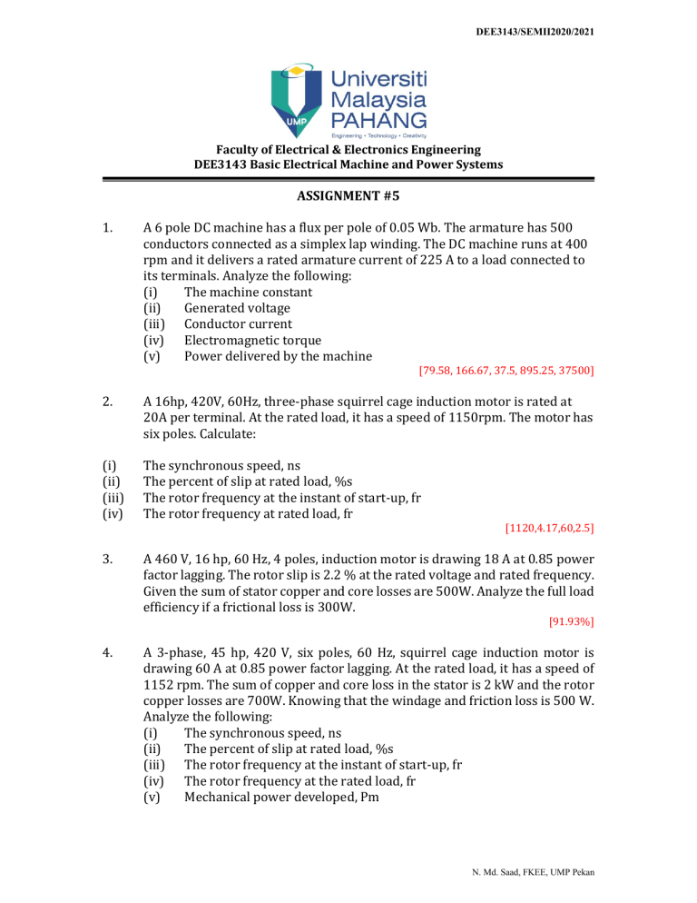
DEE3143/SEMII2020/2021 Faculty of Electrical & Electronics Engineering DEE3143 Basic Electrical Machine and Power Systems ASSIGNMENT #5 1. A 6 pole DC machine has a flux per pole of 0.05 Wb. The armature has 500 conductors connected as a simplex lap winding. The DC machine runs at 400 rpm and it delivers a rated armature current of 225 A to a load connected to its terminals. Analyze the following: (i) The machine constant (ii) Generated voltage (iii) Conductor current (iv) Electromagnetic torque (v) Power delivered by the machine [79.58, 166.67, 37.5, 895.25, 37500] 2. A 16hp, 420V, 60Hz, three-phase squirrel cage induction motor is rated at 20A per terminal. At the rated load, it has a speed of 1150rpm. The motor has six poles. Calculate: (i) (ii) (iii) (iv) The synchronous speed, ns The percent of slip at rated load, %s The rotor frequency at the instant of start-up, fr The rotor frequency at rated load, fr 3. A 460 V, 16 hp, 60 Hz, 4 poles, induction motor is drawing 18 A at 0.85 power factor lagging. The rotor slip is 2.2 % at the rated voltage and rated frequency. Given the sum of stator copper and core losses are 500W. Analyze the full load efficiency if a frictional loss is 300W. [1120,4.17,60,2.5] [91.93%] 4. A 3-phase, 45 hp, 420 V, six poles, 60 Hz, squirrel cage induction motor is drawing 60 A at 0.85 power factor lagging. At the rated load, it has a speed of 1152 rpm. The sum of copper and core loss in the stator is 2 kW and the rotor copper losses are 700W. Knowing that the windage and friction loss is 500 W. Analyze the following: (i) The synchronous speed, ns (ii) The percent of slip at rated load, %s (iii) The rotor frequency at the instant of start-up, fr (iv) The rotor frequency at the rated load, fr (v) Mechanical power developed, Pm N. Md. Saad, FKEE, UMP Pekan DEE3143/SEMII2020/2021 (vi) (vii) The efficiency of the motor, ɲ Draw the power flow diagram of the induction motor [Hint: 1 hp = 746 W] [1200,4,60,2.4,34400.53,91.37%] 5. A 20 kVA, 2000/400V transformer has the resistance and reactance as shown in Table 1. The shunt magnetizing impedance is neglected. Analyze the following: (i) Draw the exact equivalent circuit of real transformer. (ii) The turn ratio. (iii) The parameters referred to high voltage side and draw the equivalent circuit. (iv) The parameters referred to low voltage side and draw the equivalent circuit. (v) Refer to high voltage side, calculate the approximate value of secondary voltage at full load of 0.8 lagging power factor, when primary supply is 2000V. Primary Side Secondary Side Table 1 Resistance 3Ω 0.3Ω Reactance 12Ω 0.1Ω [5, 10.5+j14.5, 0.42+j0.58, 365.95∟1.7o] 6. A 1000VA, 230/115V, single-phase transformer has been tested to determine its equivalent circuit. The results of test are shown in Table 2. All data given were taken from the primary side of the transformer. Analyze: (i) The equivalent circuit referred to the high-voltage side. (ii) Equivalent circuit referred to the low-voltage side. (iii) Voltage regulation for full load at 0.8 power factor lagging. (iv) The efficiency of the transformer under the condition in part (iii). Voltage Current Power Table 2 Open-circuit test 230V 0.22A 25W Short-circuit test 17.1V 8.7A 38.1W [VR=2.94%, efficiency, n =95.69%] Please submit your assignment by 13 June 2021 before 11.59pm. N. Md. Saad, FKEE, UMP Pekan

