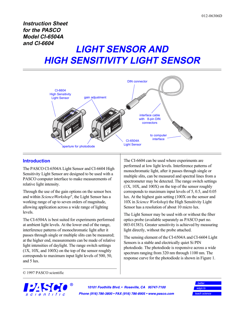
012-06306D Instruction Sheet for the PASCO Model CI-6504A and CI-6604 LIGHT SENSOR AND HIGH SENSITIVITY LIGHT SENSOR DIN connector CI-6604 High Sensitivity Light Sensor 10 0 1 10 gain adjustment GA IN Y IT IV IT OR NSNS E E S S GHHT 04 HILIG 66 10 0 1 GA IN 4A 10 I- C 50 I-6 C T GH R LINSO E S aperture for photodiode Introduction The PASCO CI-6504A Light Sensor and CI-6604 High Sensitivity Light Sensor are designed to be used with a PASCO computer interface to make measurements of relative light intensity. Through the use of the gain options on the sensor box and within ScienceWorkshop®, the Light Sensor has a working range of up to seven orders of magnitude, allowing application across a wide range of lighting levels. The CI-6504A is best suited for experiments performed at ambient light levels. At the lower end of the range, interference patterns of monochromatic light after it passes through single or multiple slits can be measured; at the higher end, measurements can be made of relative light intensities of daylight. The range switch settings (1X, 10X, and 100X) on the top of the sensor roughly corresponds to maximum input light levels of 500, 50, and 5 lux. © 1997 PASCO scientific interface cable with 8-pin DIN connectors CI-6504A Light Sensor to computer interface The CI-6604 can be used where experiments are performed at low light levels. Interference patterns of monochromatic light, after it passes through single or multiple slits, can be measured and spectral lines from a spectrometer may be detected. The range switch settings (1X, 10X, and 100X) on the top of the sensor roughly corresponds to maximum input levels of 5, 0.5, and 0.05 lux. At the highest gain setting (100X on the sensor and 10X in Science Workshop) the High Sensitivity Light Sensor has a resolution of about 10 micro lux. The Light Sensor may be used with or without the fiber optics probe (available separately as PASCO part no. 003-01383). Greater sensitivity is achieved by measuring light directly, without the probe attached. The sensing element of the CI-6504A and CI-6604 Light Sensors is a stable and electrically quiet Si PIN photodiode. The photodiode is responsive across a wide spectrum ranging from 320 nm through 1100 nm. The response curve for the photodiode is shown in Figure 1. Light Sensor and High Sensitivity Light Sensor 012-06306D B A Spectral Response ScienceWorkshop™ RES 1 L O A s ANALOG CHANNELS B n C 2 G O ® Interface ON DIGITAL CHANNELS GAIN=1,10:ISOLATED GAIN = 1,10: REF TO GND GAIN = 1: REF TO GND 0.6 ScienceWorkshop™ 500 P T 0.4 O 10 100 1 GA RES 1 ® L O A s ANALOG CHANNELS B n C Interface 2 G Plug into any analog channel. 0.5 S ON DIGITAL CHANNELS GAIN=1,10:ISOLATED GAIN = 1,10: REF TO GND GAIN = 1: REF TO GND IN 4A 50 I-6 C HTR O LIG NS SE 0.3 Plug into any analog channel. 0.2 0.1 T H OR IG S L N E S RELATI VE SENSI TI VI TY T 0.7 S P 500 4A -650 800 1000 GAIN 1 600 WAVELENGTH (nm) 10 400 100 CI 0 200 Figure 2. Connecting the Light Sensor and the computer interface Figure 1. Spectral response curve of the photodiode ➁ If the fiber optics probe (PASCO part no. The Light Sensor can be plugged directly into any PASCO computer interface box or can be connected to the interface box using the supplied cable with DIN connectors. 003-01383) is to be used, attach it by slipping the connector of the fiber optics probe over the input connector on the Light Sensor (Figure 3). A quarter twist clockwise locks the probe to the Light Sensor. (To disconnect, press the connector towards the sensor box, turn it counterclockwise one-quarter turn, and pull away from the box.) Equipment Included: • Light Sensor • 6-foot cable with 8-pin DIN connectors 10 0 Additional Equipment Required: • Any PASCO computer interface (300, 500, or 700 ScienceWorkshop® series for Macintosh or Windows or the 6500 series interface for DOS) 1 GA IN 4A 10 Rotate ring one-quarter turn to secure ➤ Note: The manual has been written with the assumption that the user has a basic familiarity with Science Workshop and has access to the User’s Guide for Science Workshop. Users can gain basic skills with Science Workshop by working through the tutorial within Science Workshop. Another useful resource is the Quick Reference Card for Science Workshop. 50 I-6 C T GH R LINSO SE Light sensor probe connector Figure 3. Attaching the fiber optics probe to the Light Sensor ➂ Open the Experiment Setup window in Science Workshop. Click and drag the analog plug icon to the analog channel icon that matches the analog port you are using for the Light Sensor. Setup Procedure ➀ Connect the Light Sensor and any analog channel of the interface box with the interface cable (Figure 2A), or insert the DIN plug of the Light Sensor into the jack of any analog channel of the interface box (Figure 2B). NOTE: Use care when handling the fiber optics probe. The optical fibers inside may be damaged if the cable is bent sharply. Do not coil tighter than a 10 cm (4 in.) diameter circle. Be sure not to damage the input end of the probe; scratches may impair light transmission. 2 Light Sensor and High Sensitivity Light Sensor 012-06306D ➃ Select Light Sensor from the drop-down menu. ➂ Use the calibration window in Science Workshop to calibrate the Light Sensor. The sensor may be calibrated in relative units such as percent of sensor voltage output. If a standard is used, the Light Sensor output may also be referenced to absolute units such as lux. Refer to the User's Guide for Science Workshop for more details concerning calibration. ➄ Open a display window, such as the Digits display, by dragging and dropping the appropriate display icon on the Light Sensor icon. ➅ Select the appropriate gain setting on the sensor box for the light levels to be measured (Figure 4). The correct gain setting is the one for which the intensity levels on the display vary appropriately for measuring the relative light intensity changes in your experiment. Mounting on an Experimental Apparatus ➀ Use the 1/4-20 threaded connector located on the bottom of the sensor box to secure the Light Sensor to an experimental apparatus (Figure 5). The alignment hole fits over an alignment pin included on some PASCO apparatuses. Adjust the gain for the light conditions. 10 0 1 alignment hole GA IN A 4 50 10 1/4 –20 threaded connector I-6 C T GHOR I L NS Figure 4. Setting the gain on the Light Sensor Calibration and Sensitivity Adjustment in Science Workshop Figure 5. Mounting connector and alignment hole ➀ To open the Light Sensor's calibration window, double-click on the Light Sensor icon in the Experiment Setup window. DIN Connector Specifications for CI-6504A IN GA 1 1 can adjust the sensitivity (gain) in ScienceWorkshop by selecting the appropriate level from the drop-down menu. If the Light Sensor is producing voltage above 1 V, set the sensitivity to Low (1x). If the Light Sensor is producing voltages between +1 V and 0 V, select Med (10x). With the ScienceWorkshop 700 interface, set the sensitivity to High (100x) if the voltage is very low (between +0.1 V and 0 V). Refer to the User's Guide for Science Workshop for more details concerning adjusting the sensitivity setting. 10 0 1: analog output (+), 0 to 5 V 2: analog output (-), signal ground 3: (no connection) 4: + 5 V DC power 5: power ground ➁ If the Light Sensor is in analog channel A or B, you 3 5 4 2 DIN Connector Specifications for CI-6604 IN GA 7 3 5 1 3 10 0 ➤ Note: Gain for channel C cannot be adjusted in Science Workshop. Use Channels A or B if necessary to adjust gain in Science Workshop. 10 1: analog output (+), 0 to 5 V 2: analog output (-), signal ground 6 3: (no connection) 8 4: + 5 V DC power 1 5: power ground 4 6: +12 VDC power 2 7: -12 VDC power 8: (no connection) Light Sensor and High Sensitivity Light Sensor 012-06306D Copyright, Warranty, and Equipment Return Please—Feel free to duplicate this manual subject to the copyright restrictions below. Copyright Notice Equipment Return The PASCO scientific 012-06306C instruction sheet is copyrighted and all rights reserved. However, permission is granted to non-profit educational institutions for reproduction of any part of the Light Sensor instruction sheet providing the reproductions are used only for their laboratories and are not sold for profit. Reproduction under any other circumstances, without the written consent of PASCO scientific, is prohibited. Should the product have to be returned to PASCO scientific for any reason, notify PASCO scientific by letter, phone, or fax BEFORE returning the product. Upon notification, the return authorization and shipping instructions will be promptly issued. ➤ NOTE: NO EQUIPMENT WILL BE ACCEPTED FOR RETURN WITHOUT AN AUTHORIZATION FROM PASCO. Limited Warranty When returning equipment for repair, pack the units properly. Carriers will not accept responsibility for damage caused by improper packing. To be certain the unit will not be damaged in shipment, observe the following rules: PASCO scientific warrants the product to be free from defects in materials and workmanship for a period of one year from the date of shipment to the customer. PASCO will repair or replace, at its option, any part of the product which is deemed to be defective in material or workmanship. The warranty does not cover damage to the product caused by abuse or improper use. Determination of whether a product failure is the result of a manufacturing defect or improper use by the customer shall be made solely by PASCO scientific. Responsibility for the return of equipment for warranty repair belongs to the customer. Equipment must be properly packed to prevent damage and shipped postage or freight prepaid. (Damage caused by improper packing of the equipment for return shipment will not be covered by the warranty.) Shipping costs for returning the equipment after repair will be paid by PASCO scientific. ➀ The packing carton must be strong enough for the item shipped. ➁ Make certain there are at least two inches of packing material between any point on the apparatus and the walls of the carton. ➂ Make certain that the packing material can not shift in the box or become compressed, allowing the instrument to come in contact with the edge of the packing carton. The exclamation point within an equilateral triangle is intended to alert the user of the presence of important operating and maintenance (servicing) instructions in the literature accompanying the device. 4 Address: PASCO scientific 10101 Foothills Blvd. P.O. Box 619011 Roseville, CA 95747-7100 Phone: FAX: email: web: (916) 786-3800 (916) 786-3292 techsupp@pasco.com www.pasco.com


