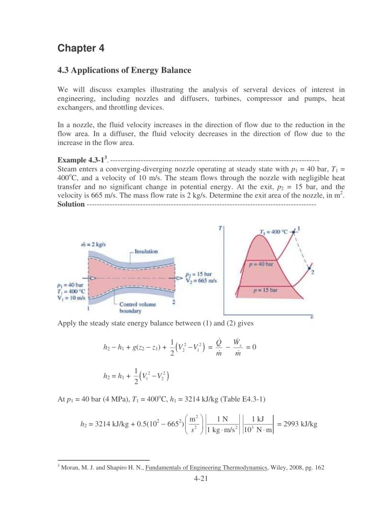
Chapter 4 4.3 Applications of Energy Balance We will discuss examples illustrating the analysis of serveral devices of interest in engineering, including nozzles and diffusers, turbines, compressor and pumps, heat exchangers, and throttling devices. In a nozzle, the fluid velocity increases in the direction of flow due to the reduction in the flow area. In a diffuser, the fluid velocity decreases in the direction of flow due to the increase in the flow area. Example 4.3-13. ---------------------------------------------------------------------------------Steam enters a converging-diverging nozzle operating at steady state with p1 = 40 bar, T1 = 400oC, and a velocity of 10 m/s. The steam flows through the nozzle with negligible heat transfer and no significant change in potential energy. At the exit, p2 = 15 bar, and the velocity is 665 m/s. The mass flow rate is 2 kg/s. Determine the exit area of the nozzle, in m2. Solution ------------------------------------------------------------------------------------------ Apply the steady state energy balance between (1) and (2) gives h2 − h1 + g(z2 − z1) + h2 = h1 + W 1 2 Q V2 − V12 ) = − s =0 ( m m 2 1 2 V1 − V22 ) ( 2 At p1 = 40 bar (4 MPa), T1 = 400oC, h1 = 3214 kJ/kg (Table E4.3-1) h2 = 3214 kJ/kg + 0.5(102 − 6652) 3 m2 s2 1 kJ 1N = 2993 kJ/kg 3 2 1 kg ⋅ m/s 10 N ⋅ m Moran, M. J. and Shapiro H. N., Fundamentals of Engineering Thermodynamics, Wiley, 2008, pg. 162 4-21 Table E4.3-1 Steam properties 1 2 Temp Pressure C MPa 400 4 280.1 1.5 Specific Volume m3/kg 0.07341 0.1628 Internal Specific Energy Enthalpy kJ/kg kJ/kg 2920 3214 2749 2993 Specific Entropy kJ/kg/K 6.769 6.839 Quality Phase Dense Fluid (T>TC) Superheated Vapor At p2 = 15 bar (1.5 MPa), h2 = 2993 kJ/kg, v2 = 0.1628 m3/kg The exit area is then mv2 (2 kg)(0.1628 m3 /kg) A2 = = = 4.9× ×10-4 m2 V2 665 m/s Example 4.3-24. ---------------------------------------------------------------------------------Steam enters a turbine operating at steady state with a mass flow rate of 4600 kg/h. The turbine develops a power output of 1000 kW. At the inlet, the pressure is 60 bar, the temperature is 400oC, and the velocity is 10 m/s. At the exit, the pressure is 0.1 bar, the quality is 0.9, and the velocity is 30 m/s. Calculate the rate of heat transfer between the turbine and surroundings, in kW. Solution ------------------------------------------------------------------------------------------ Apply the steady state energy balance between (1) and (2) gives h2 − h1 + g(z2 − z1) + Solving for W 1 2 Q V2 − V12 ) = − s ( m m 2 Q with g(z2 − z1) = 0,we obtain m W 1 Q = s + h2 − h1 + (V22 − V12 ) m m 2 Properties of steam for states (1) and (2) are listed in Table E4.3-2 4 Moran, M. J. and Shapiro H. N., Fundamentals of Engineering Thermodynamics, Wiley, 2008, pg. 165 4-22 Table E4.3-2 Steam properties 1 2 Temp Pressure C MPa 400 6 45.81 0.01 Specific Volume m3/kg 0.04739 13.21 Internal Specific Energy Enthalpy kJ/kg kJ/kg 2893 3177 2213 2345 Specific Entropy kJ/kg/K 6.541 7.4 Quality Phase Dense Fluid (T>TC) 0.9 Liquid Vapor Mixture The change in kinetic energy is evaluated: 1 2 m2 2 2 2 V − V = 0.5(30 − 10 ) (2 1) 2 s2 1 kJ 1N = 0.4 kJ/kg 3 2 1 kg ⋅ m/s 10 N ⋅ m The change in enthalpy is h2 − h1 = 2345 kJ/kg − 3177 kJ/kg = − 832 kJ/kg W W 1 Q = s + h2 − h1 + (V22 − V12 ) = s − 832 kJ/kg + 0.4 kJ/kg m m m 2 W Q = s − 831.6 kJ/kg m m Q = 1000 kW − 4600 kg 1 h 1 kW (831.6 kJ/kg) = − 62.6 kW h 3600 s 1 kJ/s Heat transfer from the turbine to the surroundings. Example 4.3-35. ---------------------------------------------------------------------------------Air enters a compressor operating at steady state at a pressure of 1 bar, a temperature of 290 K, and a velocity of 6 m/s through an inlet area of 0.1 m2. At the exit, the pressure is 7 bar, the temperature is 450 K, and the velocity is 2 m/s. Heat transfer from the compressor to its surroundings occurs at a rate of 180 kJ/min. Employing the ideal gas model, calculate the power input to the compressor, in kW. Solution ------------------------------------------------------------------------------------------ 5 Moran, M. J. and Shapiro H. N., Fundamentals of Engineering Thermodynamics, Wiley, 2008, pg. 168 4-23 Apply the steady state energy balance between (1) and (2) gives h2 − h1 + g(z2 − z1) + W 1 2 Q V2 − V12 ) = − s ( m m 2 Solving for Ws with g(z2 − z1) = 0,we obtain V12 − V22 Ws = Q + m ( h1 − h2 ) + 2 The mass flow rate is given by m = AV 1 1 v1 The specific velocity can be determine from ideal gas law v1 = ( R / M )T 1 p1 = 8314 N ⋅ m (290 K) 28.97 kg ⋅ K = 0.8324 kg/m3 5 2 10 N/m The mass flow rate is then 0.1 m 2 ) ( 6 m/s ) ( AV 1 1 m = = = 0.7209 kg/s v1 0.8324 kg/m3 The change in air enthalpy can be obtained from CATT2 program h1 − h2 = 290.6 kJ/kg − 452.3 kJ/kg = −161.7 kJ/kg Table E4.3-3 Air properties from CATT2 Temp K 290 450 Pressure MPa 0.1 0.7 Specific Enthalpy (Mass) kJ/kg 290.6 452.3 The change in kinetic energy is evaluated: 1 2 m2 2 2 2 V − V = 0.5(6 − 2 ) ( 1 2) 2 s2 1 kJ 1N = 0.02 kJ/kg 3 2 1 kg ⋅ m/s 10 N ⋅ m The power input to the compressor is then 4-24 Ws = Q + m ( h1 − h2 ) + Ws = − V12 − V22 2 180 kJ + (0.7209 kg/s)(−161.7 + 0.02) kJ/kg = − 119.6 kW 60 s 4.4 Heat Exchanger Heat exchangers are devices for transferring heat between two fluid streams. Heat exchangers can be classified as indirect contact type and direct contact type. Indirect contact type heat exchangers have no mixing between the hot and cold streams, only energy transfer is allowed as shown in Figure 4.4-1. Hot fluid Cold fluid Wall separates streams Figure 4.4-1 Indirect contact type heat exchanger. Direct contact type heat exchangers have no wall to separate the cold from the hot streams as shown in Figure 4.4-2. Noncondensible bleed Warm water Steam Cold water Figure 4.4-2 Direct contact type heat exchanger. We will briefly discuss two types of tubular heat exchangers: concentric tube and shell-andtube heat exchangers. A concentric tube or double pipe heat exchanger is the simplest heat exchanger for which the hot and cold fluids move in the same or opposite directions as shown in Figure 4.4-3. 4-25 Hot fluid Hot fluid Cold fluid Cold fluid Counter flow Parallel flow Figure 4.4-3 Concentric tube heat exchangers. Shell-and-tube heat exchanger is the most common configuration. There are many different forms of shell-and-tube heat exchangers according to the number of shell-and-tube passes. A common form with one shell pass and two tube passes is shown in Figure 4.4-4. Baffles are usually installed to increase the heat transfer coefficient of the fluid by introducing turbulence and cross-flow in the shell side. Baffles Shell inlet Tube oulet Tube inlet Shell outlet Figure 4.4-4a Shell-and-tube heat exchanger with one shell pass and two tube passes. Figure 4.4-4b Details construction of a shell-and-tube heat exchanger. 4-26 Example 4.4-1. ---------------------------------------------------------------------------------Saturated steam at 99.63oC condenses on the outside of a 5-m long, 4-cm-diameter thin horizontal copper tube by cooling liquid water that enters the tube at 25oC at an average velocity of 3 m/s and leaves at 45oC. Liquid water density is 997 kg/m3, cp of liquid water is 4.18 kJ/kgoC. (a) Determine the rate of heat transfer to water. (b) If the rate of heat transfer to water is 200 kW, determine the rate of condensation of steam Solution -----------------------------------------------------------------------------------------Condensing steam Q Te Ti (a) The rate of heat transfer to water is given by Q = m cp(Te − Ti) In this equation, the mass flow rate of water is given by m = ρVvelAtube m = (997 kg/m3)(3 m/s)(π×0.022 m2) = 3.7586 kg/s The heat transfer rate is then Q = (3.7586 kg/s)(4.18 kJ/kgoC)(45 − 25)oC = 314.2 kW (b) If the rate of heat transfer to water is 200 kW, determine the rate of condensation of steam. We need the enthalpy for saturated liquid and saturated vapor Temp C 99.63 99.63 Specific Pressure Enthalpy MPa kJ/kg 0.1 2675 0.1 417.5 Quality Phase 1 0 Saturated Vapor Saturated Liquid The rate of heat transfer to water can also be determined from Q = msteam (hg − hf) msteam = msteam = Q hg − h f 200 kJ/s = 0.0886 kg/s (2675 - 417.5) kJ/kg 4-27 Example 4.4-2. ---------------------------------------------------------------------------------A light oil is to be preheated before being fed to a distillation tower. The preheating is to be accomplished in a heat exchanger in which the heating medium is hot oil. The following data are available: Light oil Hot oil Mass flow rate, kg/hr 160,000 120,000 1.7 1.8 Heat capacity, kJ/kg⋅K 300 500 Entry temperature, K 1) If the light oil leaves the heat exchanger at 360 K, determine the temperature of the exit hot oil. 2) If the two fluids flow co-currently through the heat exchanger, determine the maximum attainable temperature of the light oil. 3) If the two fluids flow counter-currently through the heat exchanger, determine the maximum attainable temperature of the light oil. Solution -----------------------------------------------------------------------------------------1) Determine the temperature of the exit hot oil. Q = mc cpc(Tce − Tci) = mh cph(Thi − The) The = 500 K − The = Thi − mc c pc mh c ph (Tce − Tci) (160, 000)(1.7) (360 − 300) K = 424.4 K (120, 000)(1.8) 2) If the two fluids flow co-currently through the heat exchanger, determine the maximum attainable temperature of the light oil. For cocurrent flow, the maximum attainable temperatrue of the light oil is Tce = The mc cpc(Tce − Tci) = mh cph(Thi − Tce) Tce = Tce = mc c pcTci + mh c phThi mc c pc + mh c ph (16)(1.7)(300 K) + (12)(1.8)(500 K) = 388.5 K (16)(1.7) + (12)(1.8) 3) If the two fluids flow counter-currently through the heat exchanger, determine the maximum attainable temperature of the light oil. Since mc cpc = (160,000)(1.7) = 272,000 kJ/hr⋅s > mh cph = (120,000)(1.8) = 216,000 kJ/hr⋅s The = Tci mc cpc(Tce − Tci) = mh cph(Thi − Tci) Tce = 300 K + Tce = Tci + (120, 000)(1.8) (500 − 300) K = 458.8 K (160, 000)(1.7) 4-28 mh c ph mc c pc ( Thi − Tci)
