Power Systems Load Flow Assignment: Gauss-Seidel & Newton-Raphson
advertisement

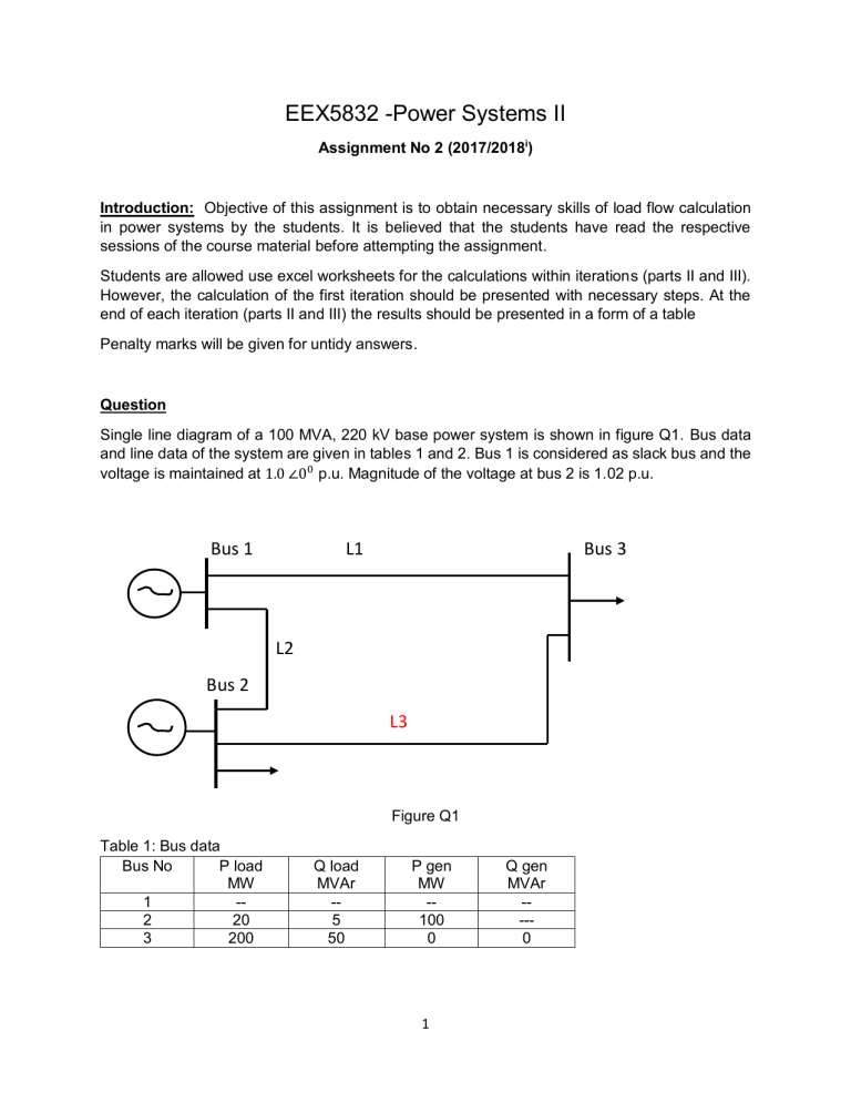
EEX5832 -Power Systems II Assignment No 2 (2017/2018i) Introduction: Objective of this assignment is to obtain necessary skills of load flow calculation in power systems by the students. It is believed that the students have read the respective sessions of the course material before attempting the assignment. Students are allowed use excel worksheets for the calculations within iterations (parts II and III). However, the calculation of the first iteration should be presented with necessary steps. At the end of each iteration (parts II and III) the results should be presented in a form of a table Penalty marks will be given for untidy answers. Question Single line diagram of a 100 MVA, 220 kV base power system is shown in figure Q1. Bus data and line data of the system are given in tables 1 and 2. Bus 1 is considered as slack bus and the voltage is maintained at 1.0 ∠00 p.u. Magnitude of the voltage at bus 2 is 1.02 p.u. Bus 1 L1 Bus 3 L2 Bus 2 L3 Figure Q1 Table 1: Bus data Bus No P load MW 1 -2 20 3 200 Q load MVAr -5 50 P gen MW -100 0 1 Q gen MVAr ---0 Table 2: Line data Line L1 L2 L3 R (Ω) 5 4 4 XΩ j40 j30 j50 Part I a. Draw impedance diagram of the system b. Form bus admittance matrix for the system [15 marks] Part II Calculate voltage at buses using Gauss-Seidel method. Accuracy of the results should be less than 0.1 p.u (ε<=0.1 p.u.) [25 marks] Part III Calculate voltage at buses using Newton-Raphson method. Power mismatch should be less than 0.1 p.u. (you may use formula given in moodle class (http://elearn.ou.ac.lk ) for Jakobian matrix element calculation) [25 marks] Part VI a. Based on the results obtained in parts II and III, give your comments on above two methods of load flow calculations with reference to number of iterations, calculation time per iteration, convergence. b. Calculate power flow through the lines using the results obtained in part II or part III (if the last digit of your registration number is even – use results of part II, if the last digit of your registration number is odd – use the results of part III) c. Sketch the power flow diagram d. Calculate slack bus power and power factor e. Calculate total loss of the system and express as a percentage f. Suppose reactive power of the generator at bus 2 obtained (in part II or III) is beyond the actual reactive power limit of the generator at bus 2, explain how you proceed with the calculation (no calculation is required) g. Perform one iteration of “decoupled load flow calculation” and compare the results with the results obtained in part II and III [35 marks] 2

