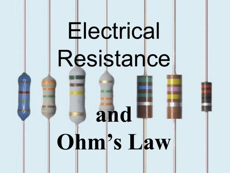
Electrical Resistance and Ohm’s Law Objective: S1-3-12 Describe resistance in terms of the particle model of electricity. Electrical Resistance and Ohm’s Law • In order for us to use electricity, electrical energy is changed into heat, sound, light, and mechanical energy. Devices used to do this are called electrical loads. ELECTRICAL RESISTANCE 1. Energized electrons flow through a circuit. They transfer energy to the conductors and to the electrical load. 2. The ability of conductors and electrical loads to slow down the flow of electrons is called electrical resistance(R). 3. A resistor is a component of an electrical load that resists the passage of electrons (electrical current) and converts electrical energy into other forms (ex. filament of light bulb). Electrical Resistance 4. Resistors are sometimes used to reduce the energy of a circuit for safety reasons. 5. Electrical resistance causes a loss of electric potential (voltage). 6. Electrical Resistance (R) is measured in Ohms Ω. Analogy CONSIDER THE FOLLOWING… A neat analogy to help understand these terms is a system of plumbing pipes. The voltage is equivalent to the water pressure, the current is equivalent to the flow rate, and the resistance is like the pipe size. Ohm’s Law • George Ohm was a scientist who experimented with electricity and resistance. The unit of resistance, called ohms, was named after him. While he was experimenting with electricity, he discovered a law that links amperes, volts, and ohms. This law is called Ohm’s Law. Calculating Ohm’s Law • An easy way to calculate resistance is by using the following equation: V= Volts I= Current (Measured in Amps) R= Resistance • The triangle can be put into three equations: V= I·R V R= I V I= R Example1 A bulb that has 2.4 A flowing through it, has a resistance of 16 Ω. Calculate the voltage drop (energy lost by the electrons to light up the bulb) across the load. e- + 38.4 V - e● ● Example 2 A 9 V battery is hooked up to a metal wire to make a circuit. If the metal wire has a resistance of 6.5 Ω, calculate the current in the wire. e- + - e- ● ● Voltmeter: • Placed parallel across the circuit • Measures potential drop of the load. Ammeter: • Placed in series with the circuit. • Measures current traveling through. Resistors in Series • Current is the same through each resistor. • Voltage across each resistor is different. • Total resistance of the circuit equals the added up values of the individual resistors: Equivalent resistance of resistors in series : R = R1 + R2 + R3 + ... 10 V If the values of the three resistors are: R1 = 8 Ω R1 = 8 Ω R1 = 4 Ω Resistors in Parallel • Current in a parallel circuit splits up. • Voltage across each resistor in parallel is same. • Total resistance of the circuit equals the added up reciprocals of the resistance values, and then taking the reciprocal of the total: Equivalent resistance of resistors in parallel: 1 / R = 1 / R1 + 1 / R2 + 1 / R3 +... 10 V If the values of the three resistors are: R1 = 8 Ω R1 = 8 Ω R1 = 4 Ω Amount of current through each resistor depends on the resistance: Individual currents can be found with V = IR: I1 = 10 / 8 I2 = 10 / 8 I3 = 10 / 4 Note that the currents add together to 5 A, the total current. Complete Resistance and Ohm’s Law Word Problems •Due tomorrow unless otherwise noted


