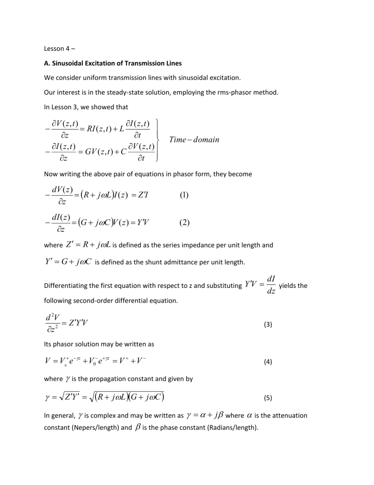
Lesson 4 – A. Sinusoidal Excitation of Transmission Lines We consider uniform transmission lines with sinusoidal excitation. Our interest is in the steady-state solution, employing the rms-phasor method. In Lesson 3, we showed that V ( z , t ) I ( z , t ) RI ( z , t ) L z t I ( z , t ) V ( z , t ) GV ( z , t ) C z t Time domain Now writing the above pair of equations in phasor form, they become dV ( z ) R jL I ( z ) Z I z (1) dI ( z ) G jC V ( z ) Y V z (2) where Z R jL is defined as the series impedance per unit length and Y G jC is defined as the shunt admittance per unit length. Differentiating the first equation with respect to z and substituting Y V dI yields the dz following second-order differential equation. d 2V Z Y V z 2 (3) Its phasor solution may be written as V V0 e z V0 e z V V where (4) is the propagation constant and given by Z Y R jL G jC (5) is complex and may be written as j where is the attenuation constant (Nepers/length) and is the phase constant (Radians/length). In general, The phasor quantities V and V are functions of z and represent the forward and reverse voltage waves on the line. V0 and V 0 represent the values at z=0, the input end. Substitution of Eq. 4 into the first of Eq.2 yields the accompanying solution for I. I I 0 e z I 0 e z I I 0 where I The quantity V0 and I Z0 V0 Z0 Z 0 is known as the characteristic impedance of the transmission line and is given by Z Y Z0 0 (6) R j L G j C Ohms (7) It is the voltage – to – current ratio for the travelling waves. That is Z0 V I I I (8) The reciprocal of Z 0 is defined as the characteristic impedance ( Y0 ) of the line and therefore Y0 1 Z0 Y Z Mhos (9) Since the voltages and currents in Eq.4 and Eq.6 are phasor quantities, they are generally complex and depend upon the specific conditions at the generator and load. The determination of their values is as follows: From ac theory, the net average power flow at any point on the line is related to V and I by P Re VI * VI cos pf where * denotes the complex conjugate and (10) pf the power factor angle. V and I represent rms values. Tutorial Problem 1 A coaxial line has the following characteristics at 1000 MHz: R 4 / m, L 450 nH / m, G 7 104 Mho / m, C 50 pF / m. (i) Calculate Z 0 , , , v, and at 1 GHz. (ii) With V0 100 V and V0 0 , calculate V, I and Pat z=4 m. B. Low=loss lines Certain conclusions can be drawn from the above example. First of all, for low-loss lines at high frequencies, R L and G C . In the microwave range, these inequalities are almost always true. Applying these approximations to Eqs.7 and 5 yields Z0 Z Y R GZ 0 2Z 0 2 LC Since (11) Np / length (12) Rad / length (13) / v, f v and f0 c v 1 LC (14) and 0 v 0 c c LC (15) Summary: 1. The equations Z 0 , , v, and are approximately the same as those for loss-less lines. 2. Since Z 0 is practically real, the average power flow in a travelling wave at any point on the line is simply the product of the rms voltage and current at that point. That is P V I and P V I . 3. For single frequency signals, the only appreciable effect of finite R and G’ is the introduction of some attenuation to the voltage and current waves as they propagate. Their amplitudes are reduced by e e 2z . z when they travel a distance z , and hence the power flow is attenuated by
