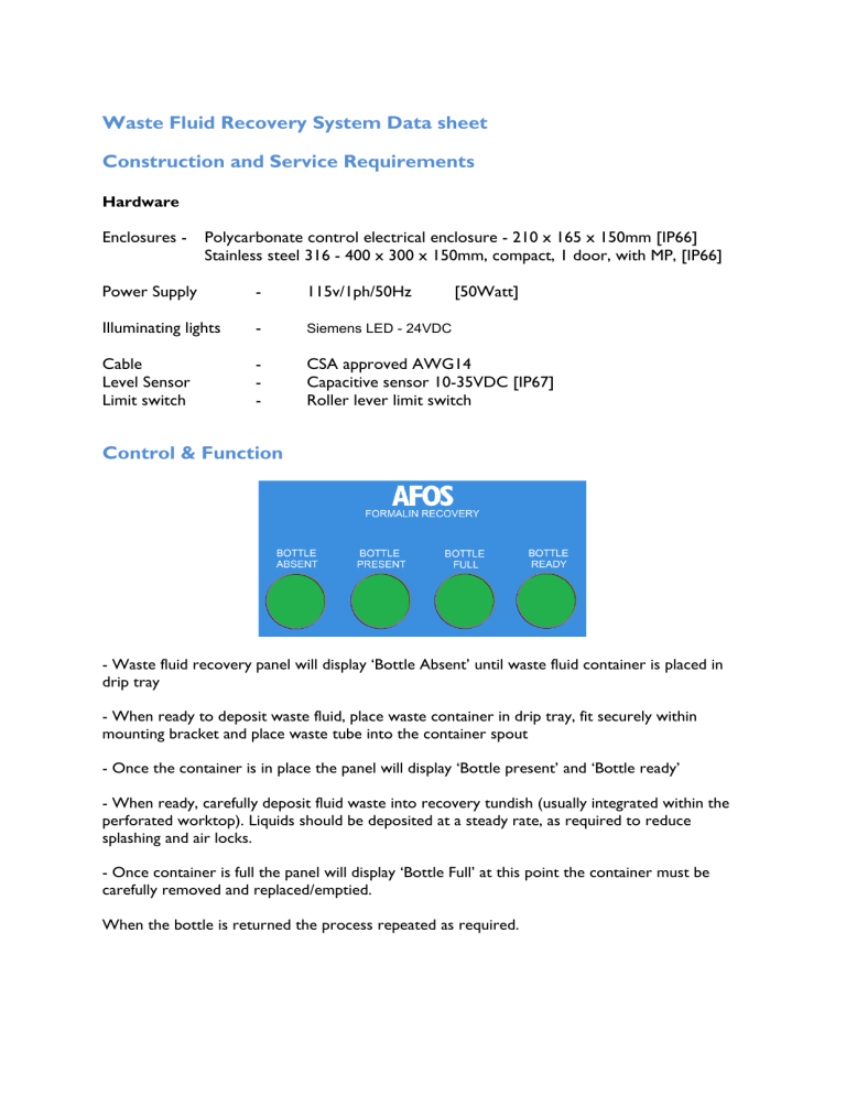
Waste Fluid Recovery System Data sheet Construction and Service Requirements Hardware Enclosures - Polycarbonate control electrical enclosure - 210 x 165 x 150mm [IP66] Stainless steel 316 - 400 x 300 x 150mm, compact, 1 door, with MP, [IP66] Power Supply - 115v/1ph/50Hz [50Watt] Illuminating lights - Siemens LED - 24VDC Cable Level Sensor Limit switch - CSA approved AWG14 Capacitive sensor 10-35VDC [IP67] Roller lever limit switch Control & Function - Waste fluid recovery panel will display ‘Bottle Absent’ until waste fluid container is placed in drip tray - When ready to deposit waste fluid, place waste container in drip tray, fit securely within mounting bracket and place waste tube into the container spout - Once the container is in place the panel will display ‘Bottle present’ and ‘Bottle ready’ - When ready, carefully deposit fluid waste into recovery tundish (usually integrated within the perforated worktop). Liquids should be deposited at a steady rate, as required to reduce splashing and air locks. - Once container is full the panel will display ‘Bottle Full’ at this point the container must be carefully removed and replaced/emptied. When the bottle is returned the process repeated as required.
