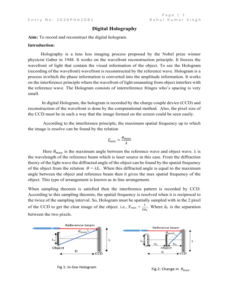
Page | 1 Rahul Kumar Singh Entry No: 2020PHA2081 Digital Holography Aim: To record and reconstruct the digital hologram. Introduction: Holography is a lens less imaging process proposed by the Nobel prize winner physicist Gaber in 1948. It works on the wavefront reconstruction principle. It freezes the wavefront of light that contain the visual information of the object. To see the Hologram (recording of the wavefront) wavefront is reconstructed by the reference wave. Hologram is a process in which the phase information is converted into the amplitude information. It works on the interference principle where the wavefront of light emanating from object interfere with the reference wave. The Hologram consists of interreference fringes who’s spacing is very small. In digital Hologram, the hologram is recorded by the charge couple device (CCD) and reconstruction of the wavefront is done by the computational method. Also, the pixel size of the CCD must be in such a way that the image formed on the screen could be seen easily. According to the interference principle, the maximum spatial frequency up to which the image is resolve can be found by the relation fmax = 𝜃𝑚𝑎𝑥 𝜆 Here 𝜃𝑚𝑎𝑥 is the maximum angle between the reference wave and object wave. λ is the wavelength of the reference beam which is laser source in this case. From the diffraction theory of the light wave the diffracted angle of the object can be found by the spatial frequency of the object from the relation 𝜃 = λfx. . When this diffracted angle is equal to the maximum angle between the object and reference beam then it gives the max spatial frequency of the object. This type of arrangement is known as in line arrangement. When sampling theorem is satisfied then the interference pattern is recorded by CCD. According to this sampling theorem, the spatial frequency is resolved when it is reciprocal to the twice of the sampling interval. So, Hologram must be spatially sampled with in the 2 pixel 1 of the CCD to get the clear image of the object. i.e., Fmax = 2𝑑 . Where dx is the separation 𝑥 between the two pixels. Fig 1: In-line Hologram Fig 2: Change in 𝜃𝑚𝑎𝑥 Page | 2 Rahul Kumar Singh Entry No: 2020PHA2081 𝐿+𝐿0 Also, when the object is brought closed to the CCD then due to condition D≥ 2𝜆𝐹 𝑚𝑎𝑥 given by Fmax≥fmax , the maximum angle increases so the fmax also increases which will violate the condition Fmax≥fmax. Experimental Setup: The following figure is the experimental setup for the digital Holography. Fig 3: Experimental Setup for Digital Holography Methodology: 1. Recoding of Phase and amplitude: The wavefront of the object and the reference wave wavefront interfere with each other. Due to the interference phase of the object is change into the intensity. To record the film, we take a reference wave. This reference wave could be the plane wave or spherical wave whose phase and amplitude should be known. To record the phase and amplitude of the object we have we have the reference wavefront whose phase and amplitude are known. This reference wave is coherent with object wave. Let the equation for the object wave is O(x,y) = |O(x,y)|exp[j𝜑(𝑥, 𝑦)] And the reference field is R(x,y) = |R|exp[-j(2𝜋𝛼𝑦)] The intensity on the recording plate is Page | 3 Rahul Kumar Singh Entry No: 2020PHA2081 I(x,y) = |𝑜(𝑥, 𝑦)|2+ |𝑅|2 + 𝑅 ∗ 𝑂(𝑥, 𝑦)exp[j𝜑(𝑥, 𝑦)] + R𝑂∗ (𝑥, 𝑦) exp[-j(2𝜋𝛼𝑦)]. Here the first term corresponding to the object intensity and the second term corresponding to the reference wave intensity, the third term gives the virtual image, and the last term gives the image which is real. The information about the phase and amplitude part of the object is recorded using a CCD. i.e the interference fringes are recorded using a CCD. 2. Reconstruction of image: In a digital hologram the image is reconstructed using an algorithm computationally. Fig 4: Numerical Reconstruction For the reconstruction, d is distance between the image plane and the CCD plane. So, to have 𝜋 a fine image the distance d should follow the condition d3 ≥ 8𝜆 [(𝜉 − 𝑥)2 + (𝜂 − 𝑦)2 ] 2 and 𝜌=𝑑+ ∆𝜂 = (𝜉−𝑥)2 𝜆𝑑 𝑁∆𝑦 2𝑑 + (𝜂−𝑦)2 2𝑑 gives the pixel size for the reconstructed image as ∆𝜉 = 𝜆𝑑 𝑁∆𝑥 and . Also, for the effective calculation it is advisable to use the FFT (Fast Fourier Transformation). The transmission function given by the Fresnel diffraction law is 𝑖 T(ξ,η)=𝜆𝑑 exp (− ∑ ∑ 𝐸𝑅∗ 𝑖2𝜋 𝜆 (𝑘, 𝑙)𝐼(𝑘, 𝑙) exp [− 𝜉2 𝜂2 𝑑)exp(-i𝜋𝜆𝑑 (𝑁2∆𝑥 2 + 𝑁2∆𝑦 2) ∗ 𝑖𝜋 𝜆𝑑 (𝑘 2 ∆𝑥 2 + 𝑙 2 ∆𝑦 2 )] exp (𝑖2𝜋 ( 𝑘𝜉 𝑁 𝑙𝜂 + 𝑁 )]. The 𝜌 can is not approximated for the convolution theorem approach. So the pixel size obtained for the reconstructed image is ∆𝜉 = ∆𝑥 and ∆𝜂 = ∆𝑦 and it cannot varies with distance d and wavelength λ. A MATLAB code will be required for the reconstruction of the image. The code pattern should follow the following step. Entry No: 2020PHA2081 Page | 4 Rahul Kumar Singh ➢ First, the image is read which was recoded with the help of the CCD. ➢ Conversion of the image into the grayscale image. ➢ Computation of 2-D Fourier transform of the off-axis hologram which was recorded using the CCD. ➢ Locating the carrier peak frequency and then filtering out the appropriate region of the Fourier transform plane near the carrier frequency peak. ➢ The filtered region is shifted at zero frequency at Fourier transform plane. ➢ At last, computation of the inverse Fourier transforms of the dc shifted field to obtain the complex object field in the hologram plane. Expected Result: If CCD of pixel size 5 micrometre and the laser light source of wavelength 632.8nm are used to perform this experiment, then the maximum spatial frequency we get is Fmax = 100 line per mm. Also, when we are having the object of size L0 = 1mm then the CCD size depending upon the resolution will be L = (Total no of pixels X pixel size). If we consider the CCD of resolution 1024*1024 then the size of the CCD would be L= 1024*5 micrometre = 5.120mm. So, the object with the spatial frequency 100 line per mm would be recorded by the CCD. For the reconstruction of the image the accurate distance d from the CCD would give the proper result by following the Fresnel approach. Discussion: Digital holography (DH) is “the computer generation and reconstruction of holograms”. Digital Holography has many applications based on the CCD recording, storage of information of object in computer and numerical reconstruction of the image. Now a days digital holography is hot topics for the research. In one of the findings, it was found that how by using the spatial light modulator as hologram reconstruction of field in 3-d is possible. This method enables use of variable holograms in future, and it is quite possible to reconstruct the virtual moving 3D scene of the object. So, this process is again called digital holography as the hologram injected to spatial light modulator comes from the computer This method can be used to develop a 3D holographic TV system. A holographic 3D holographic TV system can be understood by three Steps (1) recording of 3D image, (2) transmission of the data, (3) display and reconstruction of the optical wave fields. In this approach, a digital hologram is recorded, this hologram data is then the digital transmitted and injected to the Spatial light modulator. Applications: ➢ ➢ ➢ ➢ ➢ ➢ ➢ It can be used for Pattern recognition. For Microscopy and Endoscopy process. Holographic memories and storage. Interferometry and contouring. For the test of civil structures. For the scanning and security purpose. Automated High resolution deformation measurement and shape analysis. Entry No: 2020PHA2081 Page | 5 Rahul Kumar Singh Conclusion: Digital Holography is a process in which we record the interference micro fringes by using CCD. For the reconstruction of the image, we use computer. A MATLAB code will be required for the reconstruction of the image in the computer. Like the Fourier Holography there is no requirement of the chemical process post recording of the interference fringes. The 𝐿+𝐿 distance between the object plane and the CCD plane should be D≥ 2𝜆𝐹 0 so that the resolving 𝑚𝑎𝑥 power of the CCD sensor is satisfied. Also, for the reconstruction process we must take care 𝜋 that distance between the image plane and CCD plane should be d3 ≥ 8𝜆 [(𝜉 − 𝑥)2 + (𝜂 − 𝑦)2 ]2 in Fresnel law. The pixel size for the reconstructed image must be ∆𝜉 = 𝜆𝑑 𝑁∆𝑥 and ∆𝜂 = 𝜆𝑑 𝑁∆𝑦 . Also, a brief discussion about the 3D Holographic TV system has been done in the discussion part. References: ➢ Fourier optics by Joseph W. Goodman. ➢ PYL 757 “Fourier optics and Holography” lectures by Prof. Joby Joseph. ➢ Introduction to Optics by Frank L. Pedrotti. ➢ Experimental demonstration of digital Holography in I.I.T Delhi Lab by Jyoti Sardana. ➢ Fourier optics and optical imaging by Prof. kedar khare. ➢ Applications of Digital Holography: From Microscopy to 3D-Television:ap. Public. 7, 12006 (2012)
