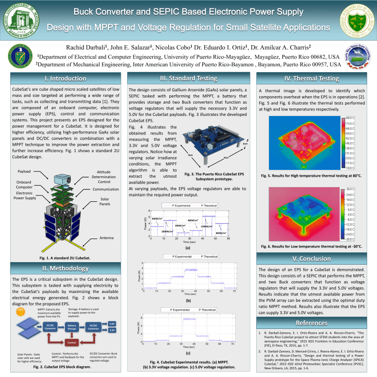
Rachid 1 Darbali , John E. 1 Salazar , Nicolas 1 Cobo Dr. Eduardo I. 1 Ortiz , Dr. Amilcar A. 2 Charris 1Department of Electrical and Computer Engineering, University of Puerto Rico-Mayagüez, Mayagüez, Puerto Rico 00682, USA 2Department of Mechanical Engineering, Inter American University of Puerto Rico-Bayamon , Bayamon, Puerto Rico 00957, USA I. Introduction III. Standard Testing IV. Thermal Testing CubeSat’s are cube shaped micro scaled satellites of low mass and size targeted at performing a wide range of tasks, such as collecting and transmitting data [1]. They are composed of an onboard computer, electronic power supply (EPS), control and communication systems. This project presents an EPS designed for the power management for a CubeSat. It is designed for higher efficiency, utilizing high-performance GaAs solar panels and DC/DC converters in combination with a MPPT technique to improve the power extraction and further increase efficiency. Fig. 1 shows a standard 2U CubeSat design. The design consists of Gallium Arsenide (GaAs) solar panels, a SEPIC tasked with performing the MPPT, a battery that provides storage and two Buck converters that function as voltage regulators that will supply the necessary 3.3V and 5.0V for the CubeSat payloads. Fig. 3 illustrates the developed CubeSat EPS. Fig. 4 illustrates the obtained results from measuring the MPPT, 2cm 3.3V and 5.0V voltage regulators. Notice how at 9cm 9cm varying solar irradiance conditions, the MPPT algorithm is able to Fig. 3. The Puerto Rico CubeSat EPS extract the utmost Subsystem prototype. available power. At varying payloads, the EPS voltage regulators are able to maintain the required power output. A thermal image is developed to identify which components overheat when the EPS is in operations [2]. Fig. 5 and Fig. 6 illustrate the thermal tests performed at high and low temperatures respectively. Payload Attitude Determination Control Onboard Computer Electronic Power Supply Communication Solar Panels P Experimental Fig. 5. Results for High temperature thermal testing at 80°C. P Theoretical Power (W) 8 6 400W/m2 4 200W/m2 2 0 Antenna 600W/m2 1200W/m2 1000W/m2 0 10 800W/m2 20 30 Time (sec) 40 50 60 Fig. 6. Results for Low temperature thermal testing at -30°C. (a) P Experimental Fig. 1. A standard 2U CubeSat. 4 4 3 2 3 2 1 1 0 0 V. Conclusion P Calculated 5 Power (W) The EPS is a critical subsystem in the CubeSat design. This subsystem is tasked with supplying electricity to the CubeSat’s payloads by maximizing the available electrical energy generated. Fig. 2 shows a block diagram for the proposed EPS. 5 Power (W) II. Methodology P Experimental P Theoretical 0 0 10 10 20 20 30 40 30Time (sec) 40 50 60 50 70 60 70 Time (sec) (b) P Experimental P Experimental PPCalculated Theoretical 5 The design of an EPS for a CubeSat is demonstrated. This design consists of: a SEPIC that performs the MPPT, and two Buck converters that function as voltage regulators that will supply the 3.3V and 5.0V voltages. Results indicate that the utmost available power from the PVM array can be extracted using the optimal duty ratio MPPT method. Results also illustrate that the EPS can supply 3.3V and 5.0V voltages. 6 Power (W) Power (W) 4 3 2 References 4 2 1 0 0 0 0 10 10 20 20 30 40 30 Time (sec)40 50 60 50 70 60 Time (sec) (c) Fig. 2. CubeSat EPS block diagram. Fig. 4. CubeSat Experimental results. (a) MPPT. (b) 3.3V voltage regulation. (c) 5.0V voltage regulation. 70 1. R. Darbali-Zamora, E. I. Ortiz-Rivera and A. A. Rincon-Charris, "The Puerto Rico CubeSat project to attract STEM students into the area of aerospace engineering," 2015 IEEE Frontiers in Education Conference (FIE), El Paso, TX, 2015, pp. 1-7. 2. R. Darbali-Zamora, D. Merced-Cirino, J. Rivera-Alamo, E. I. Ortiz-Rivera and A. A. Rincon-Charris, "Design and thermal testing of a Power Supply prototype for the Space Plasma Ionic Charge Analyzer (SPICA) CubeSat," 2015 IEEE 42nd Photovoltaic Specialist Conference (PVSC), New Orleans, LA, 2015, pp. 1-6.


