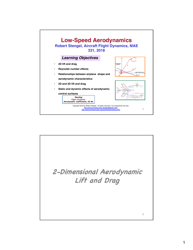
Low-Speed Aerodynamics Robert Stengel, Aircraft Flight Dynamics, MAE 331, 2018 Learning Objectives • 2D lift and drag • Reynolds number effects • Relationships between airplane shape and aerodynamic characteristics • 2D and 3D lift and drag • Static and dynamic effects of aerodynamic control surfaces Reading: Flight Dynamics Aerodynamic Coefficients, 65-84 Copyright 2018 by Robert Stengel. All rights reserved. For educational use only. http://www.princeton.edu/~stengel/MAE331.html http://www.princeton.edu/~stengel/FlightDynamics.html 1 2-Dimensional Aerodynamic Lift and Drag 2 1 Wing Lift and Drag • Lift: Perpendicular to free-stream airflow • Drag: Parallel to the free-stream airflow 3 Longitudinal Aerodynamic Forces Non-dimensional force coefficients, CL and CD, are dimensionalized by dynamic pressure, q, N/m2 or lb/sq ft reference area, S, m2 of ft2 ⎛1 ⎞ Lift = C L q S = C L ⎜ ρV 2 ⎟ S ⎝2 ⎠ ⎛1 ⎞ Drag = C D q S = C D ⎜ ρV 2 ⎟ S ⎝2 ⎠ 4 2 Circulation of Incompressible Air Flow About a 2-D Airfoil Bernoulli s equation (inviscid, incompressible flow) (Motivational, but not the whole story of lift) 1 pstatic + ρV 2 = constant along streamline = pstagnation 2 Vorticity at point x Vupper (x) = V∞ + ΔV (x) 2 γ 2−D (x) = Vlower (x) = V∞ − ΔV (x) 2 ΔV (x) Δz(x) Circulation about airfoil ΔV (x) = ∫ γ 2−D (x)dx = ∫ dx Δz(x) 0 0 c Γ 2−D c Lower pressure on upper surface 5 Relationship Between Circulation and Lift Differential pressure along chord section 2⎤ 2⎤ 1 1 ⎡ ⎡ Δp ( x ) = ⎢ pstatic + ρ∞ (V∞ + ΔV ( x ) 2 ) ⎥ − ⎢ pstatic + ρ∞ (V∞ − ΔV ( x ) 2 ) ⎥ 2 2 ⎣ ⎦ ⎣ ⎦ 2 2 1 ⎡ = ρ∞ (V∞ + ΔV ( x ) 2 ) − (V∞ − ΔV ( x ) 2 ) ⎤ ⎦ 2 ⎣ = ρ∞V∞ ΔV ( x ) = ρ∞V∞ Δz(x)γ 2−D (x) 2-D Lift (inviscid, incompressible flow) c c 0 0 ( Lift )2−D = ∫ Δp ( x ) dx = ρ ∞V∞ ∫ γ 2−D (x)dx = ρ ∞V∞ ( Γ )2−D ! 1 ρ ∞V∞ 2 c ( 2πα )[ thin, symmetric airfoil] + ρ ∞V∞ ( Γ camber )2−D 2 1 ! ρ ∞V∞ 2 c C Lα α + ρ ∞V∞ ( Γ camber )2−D 2−D 2 ( ) 6 3 Lift vs. Angle of Attack 2-D Lift (inviscid, incompressible flow) ( Lift )2-D ! ⎡⎢ ( ) 1 ⎤ ρ ∞V∞ 2 c C Lα α ⎥ + ⎡⎣ ρ ∞V∞ ( Γ camber )2−D ⎤⎦ 2−D ⎣2 ⎦ = [Lift due to angle of attack] + [Lift due to camber] 7 Typical Flow Variation with Angle of Attack • At higher angles, – flow separates – wing loses lift • Flow separation produces stall 8 4 What Do We Mean by 2-Dimensional Aerodynamics? Finite-span wing –> finite aspect ratio AR = b c = rectangular wing b × b b2 = c×b S any wing Infinite-span wing –> infinite aspect ratio 9 What Do We Mean by 2-Dimensional Aerodynamics? Assuming constant chord section, the 2-D Lift is the same at any y station of the infinite-span wing Lift 3−D = C L3−D 1 1 ρV 2 S = C L3−D ρV 2 ( bc ) [Rectangular wing] 2 2 1 Δ ( Lift 3−D ) = C L3−D ρV 2 cΔy 2 1 1 ⎛ ⎞ lim Δ ( Lift 3−D ) = lim ⎜ C L3−D ρV 2 cΔy ⎟ ⇒ "2-D Lift" ! C L2−D ρV 2 c Δy→ε >0 ⎝ ⎠ 2 2 Δy→ε >0 10 5 Effect of Sweep Angle on Lift Unswept wing, symmetric airfoil, 2-D lift slope coefficient Inviscid, incompressible flow Referenced to chord length, c, rather than wing area ⎛ ∂C ⎞ C L2−D = α ⎜ L ⎟ = α C Lα ⎝ ∂α ⎠ 2−D ( ) 2−D = ( 2π )α [Thin Airfoil Theory] Swept wing, 2-D lift slope coefficient Inviscid, incompressible flow ( ) C L2−D = α C Lα 2−D = ( 2π cos Λ )α 11 Classic Airfoil Profiles • NACA 4-digit Profiles (e.g., NACA 2412) – Maximum camber as percentage of chord (2) = 2% – Distance of maximum camber from leading edge, (4) = 40% – Maximum thickness as percentage of chord (12) = 12% • Clark Y (1922): Flat lower surface, 11.7% thickness – GA, WWII aircraft – Reasonable L/D – Benign theoretical stall characteristics – Experimental result is more abrupt Fluent, Inc,12 2007 6 Typical Airfoil Profiles Positive camber Neutral camber Negative camber Talay, NASA SP-367 13 Airfoil Effects • • Camber increases zero-α lift coefficient Thickness – increases α for stall and softens the stall break – reduces subsonic drag – increases transonic drag – causes abrupt pitching moment variation • Profile design – can reduce center-ofpressure (static margin, TBD) variation with α – affects leading-edge and trailing-edge flow separation Talay, NASA SP-367 14 7 NACA 641-012 Chord Section Lift, Drag, and Moment (NACA TR-824) CD CL, 60 Rough ~ Turbulent flap Smooth ~ Laminar CL “Drag Bucket” CL, w/o flap Cm Cm, w/o flap Cm, 60 flap α CL 15 Historical Factoid Measuring Lift and Drag with Whirling Arms and Early Wind Tunnels Whirling Arm Experimentalists Otto Lillienthal Hiram Maxim Samuel Langley Wind Tunnel Experimentalists Frank Wenham Gustave Eiffel Hiram Maxim Wright Brothers 16 8 Historical Factoid Wright Brothers Wind Tunnel 17 Flap Effects on Aerodynamic Lift • • • • Camber modification Trailing-edge flap deflection shifts CL up and down Leading-edge flap (slat) deflection increases stall α Same effect applies for other control surfaces – Elevator (horizontal tail) – Ailerons (wing) – Rudder (vertical tail) 18 9 Aerodynamic Drag 1 2 1 ρV S ≈ C D0 + ε C L2 ρV 2 S 2 2 2 1 + ε C Lo + C Lα α (* ρV 2 S )2 ( Drag = C D ≈ %'C D0 & ( ) ) 19 Parasitic Drag, CDo • Pressure differential, viscous shear stress, and separation Parasitic Drag = C D0 Talay, NASA SP-367 1 2 ρV S 2 20 10 Reynolds Number and Boundary Layer Reynolds Number = Re = ρVl Vl = µ ν where ρ = air density, kg/m 2 V = true airspeed, m/s l = characteristic length, m µ = absolute (dynamic) viscosity = 1.725 × 10 −5 kg / m i s ν = kinematic viscosity (SL) = 1.343 × 10 −5 m / s 2 21 Reynolds Number, Skin Friction, and Boundary Layer Skin friction coefficient for a flat plate Cf = Friction Drag qSwet where Swet = wetted area Wetted Area: Total surface area of the wing or aircraft, subject to skin friction Boundary layer thickens in transition, then thins in turbulent flow C f ≈ 1.33Re −1/2 ≈ 0.46 ( log10 Re ) −2.58 [laminar flow ] [turbulent flow ] 22 11 Effect of Streamlining on Parasitic Drag CD = 2.0 CD = 1.2 CD = 0.12 CD = 1.2 CD = 0.6 Talay, NASA SP-367 DRAG https://www.youtube.com/watch?v=ylh1CPqBwEw 23 Subsonic CDo Estimate (Raymer) 24 12 Historical Factoid Wilbur (1867-1912) and Orville (1871-1948) Wright • Bicycle mechanics from Dayton, OH • • Self-taught, empirical approach to flight Wind-tunnel, kite, and glider experiments Dec 17, 1903: Powered, manned aircraft flight ends in success • 25 Historical Factoids 1906: 2nd successful aviator: Alberto Santos-Dumont, standing! • – High dihedral, forward control surface • Wrights secretive about results until 1908; few further technical contributions • 1908: Glenn Curtiss et al incorporate ailerons – Separate aileron surfaces at right – Wright brothers sue for infringement of 1906 US patent (and win) • 1909: Louis Bleriot's flight across the English Channel 26 13 Description of Aircraft Configurations 27 A Few Definitions Republic F-84F Thunderstreak 28 14 Wing Planform Variables Aspect Ratio Taper Ratio b AR = rectangular wing c b × b b2 = = any wing c×b S λ= ctip tip chord = croot root chord Delta Wing Swept Trapezoidal Wing Rectangular Wing 29 Wing Design Parameters • Planform – – – – – • Aspect ratio Sweep Taper Complex geometries Shapes at root and tip Chord section – Airfoils – Twist • Movable surfaces – Leading- and trailing-edge devices – Ailerons – Spoilers • Interfaces – Fuselage – Powerplants – Dihedral angle 30 Talay, NASA SP-367 15 Mean Aerodynamic Chord, c Mean aerodynamic chord (m.a.c.) ~ mean geometric chord b2 1 c = ∫ c 2 ( y ) dy S −b 2 λ= ⎛ 2 ⎞ 1+ λ + λ =⎜ ⎟ croot ⎝ 3 ⎠ 1+ λ ctip tip chord = croot root chord 2 [for trapezoidal wing] 31 Location of Mean Aerodynamic Chord and Aerodynamic Center • Axial location of the wing s subsonic aerodynamic center (a.c.) – Determine spanwise location of m.a.c. – Assume that aerodynamic center is at 25% m.a.c. Trapezoidal Wing Elliptical Wing Mi h d-c ord lin e 32 16 3-Dimensional Aerodynamic Lift and Drag Insect Wing (flat plate) Delta Wing 33 • Washout twist – – – – – Wing Twist Effects reduces tip angle of attack typical value: 2 - 4 changes lift distribution (interplay with taper ratio) reduces likelihood of tip stall allows stall to begin at the wing root • separation burble produces buffet at tail surface, warning of stall – improves aileron effectiveness at high α Talay, NASA SP-367 34 17 Aerodynamic Strip Theory • Airfoil section may vary from tip-to-tip – Chord length – Airfoil thickness – Airfoil profile – Airfoil twist • 3-D Wing Lift: Integrate 2-D lift coefficients of airfoil sections across finite span Incremental lift along span dL = C L2−D ( y ) c ( y ) qdy = dC L3−D ( y ) dy Aero L-39 Albatros c ( y ) qdy 3-D wing lift b /2 L3− D = ∫ C L2− D ( y ) c ( y ) q dy −b /2 35 Bombardier Dash 8 Effect of Aspect Ratio on 3-Dimensional Wing Lift Slope Coefficient Handley Page HP.115 (Incompressible Flow) High Aspect Ratio (> 5) Wing # ∂C & # AR & 2 π AR C Lα % L ( = = 2π % ( $ ∂α '3−D AR + 2 $ AR + 2 ' Low Aspect Ratio (< 2) Wing C Lα = # AR & π AR = 2π % ( $ 4 ' 2 36 18 Effect of Aspect Ratio on 3-D Wing Lift Slope Coefficient (Incompressible Flow) All Aspect Ratios (Helmbold equation) C Lα = π AR 2, ) +1+ 1+ #% AR &( . $ 2 ' .+* 37 Effect of Aspect Ratio on 3-D Wing Lift Slope Coefficient All Aspect Ratios (Helmbold equation) Wolfram Alpha (https://www.wolframalpha.com/) plot(pi A / (1+sqrt(1 + (A / 2)^2)), A=1 to 20) C Lα = π AR 2, ) +1+ 1+ #% AR &( . $ 2 ' .+* 38 19 Wing-Fuselage Interference Effects • Wing lift induces – Upwash in front of the wing affects canard – Downwash behind the wing affects aft tail – Local angles of attack modified, affecting net lift and pitching moment • Flow around fuselage induces upwash on the wing, canard, and tail from Etkin 39 Longitudinal Control Surfaces Wing-Tail Configuration Flap Elevator Delta-Wing Configuration Elevator 40 20 Angle of Attack and Control Surface Deflection • Horizontal tail with elevator control surface • Horizontal tail at positive angle of attack • Horizontal tail with positive elevator deflection 41 Control Flap Carryover Effect on Lift Produced By Total Surface from Schlichting & Truckenbrodt C Lδ E C Lα vs. cf xf + cf cf (x f + cf ) 42 € 21 Bell X-1 Aileron Carryover Effect M = 0.13, Re = 1.2 x 10⁶ SP ! q − ( p − po ) q , pressure coefficient Area proportional to lift NACA-RM-L53L18, 1954 43 Lift due to Elevator Deflection Lift coefficient variation due to elevator deflection C Lδ E ! (C ) Lα ∂C L = τ htηht C Lα ∂δ E ΔC L = C Lδ E δ E ( ) ht Sht S τ ht = Carryover effect ηht = Tail efficiency factor ht = Horizontal tail lift-coefficient slope Sht = Horizontal tail reference area Lift variation due to elevator deflection ΔL = C Lδ E qSδ E 44 22 Example of Configuration and Flap Effects 45 Next Time: Induced Drag and High-Speed Aerodynamics Reading: Flight Dynamics Aerodynamic Coefficients, 85-96 Airplane Stability and Control Chapter 1 Learning Objectives Understand drag-due-to-lift and effects of wing planform Recognize effect of angle of attack on lift and drag coefficients How to estimate Mach number (i.e., air compressibility) effects on aerodynamics Be able to use Newtonian approximation to estimate lift and drag 46 23 Supplementary Material 47 Thin Airfoil Theory Downward velocity, w, at xo due to vortex at x Integral Differential dw ( xo ) = γ ( x ) dx 2π ( xo − x ) w ( xo ) = 1 2π 1 γ ( x) dx o − x) ∫ (x 0 Boundary condition: flow tangent to mean camber line w ( xo ) ⎛ dz ⎞ =α −⎜ ⎟ ⎝ dx ⎠ xo V McCormick, 1995 48 24 Thin Airfoil Theory Integral equation for vorticity 1 2π V 1 γ ( x) ⎛ dz ⎞ dx = α − ⎜ ⎟ ⎝ dx ⎠ xo − x ) o ∫ (x 0 Coordinate transformation x= 1 (1− cosθ ) 2 Solution for vorticity Coefficients ⎡ 1+ cosθ ∞ ⎤ γ = 2V ⎢ A0 + ∑ An sin nθ ⎥ sin θ ⎣ ⎦ n=1 1 π dz dθ π ∫0 dx 2 π dz An = ∫ cos nθ dθ π 0 dx A0 = α − 49 McCormick, 1995 Thin Airfoil Theory Lift, from Kutta-Joukowski theorem 1 L = ∫ ρV γ ( x ) dx = 2π A0 + π A1 0 For thin airfoil with circular arc A0 = α , A1 = 4zmax C L2−D = 2πα + 4π zmax = C Lα α + C Lo [Circular arc] =C Lα α [Flat plate] C Lα = McCormick, 1995 ∂C L = 2π ∂α 50 25 Effect of Aspect Ratio on 3-Dimensional Wing Lift Slope Coefficient • High Aspect Ratio (> 5) Wing • Wolfram Alpha plot(2 pi (a/(a+2)), a=5 to 20) • Low Aspect Ratio (< 2) Wing • Wolfram Alpha plot(2 pi (a / 4), a=1 to 2) 51 Aerodynamic Stall, Theory and Experiment • Flow separation produces stall • Straight rectangular wing, AR = 5.536, NACA 0015 • Hysteresis for increasing/decreasing α Anderson et al, 1980 52 26 Maximum Lift of Rectangular Wings Maximum Lift Coefficient, CL max Schlicting & Truckenbrodt, 1979 Angle of Attack for CL max ϕ : Sweep angle δ : Thickness ratio Aspect Ratio 53 Maximum Lift of Delta Wings with Straight Trailing Edges Maximum Lift Coefficient, CL max Angle of Attack for CL max Aspect Ratio Aspect Ratio Schlicting & Truckenbrodt, 1979 λ : Taper ratio 54 27 Typical Effect of Reynolds Number on Parasitic Drag • Flow may stay attached farther at high Re, reducing the drag from Werle* 55 * See Van Dyke, M., An Album of Fluid Motion, Parabolic Press, Stanford, 1982 Aft Flap vs. All-Moving Control Surface • Carryover effect of aft flap – Aft-flap deflection can be almost as effective as full surface deflection at subsonic speeds – Negligible at supersonic speed • Aft flap – Mass and inertia lower, reducing likelihood of mechanical instability – Aerodynamic hinge moment is lower – Can be mounted on structurally rigid main surface 56 28 Historical Factoid Samuel Pierpoint Langley (1834-1906) • Astronomer supported by Smithsonian Institution • Whirling-arm experiments • 1896: Langley's steam-powered Aerodrome model flies 3/4 mile • Oct 7 & Dec 8, 1903: Manned aircraft flights end in failure 57 Multi-Engine Aircraft of World War II Boeing B-17 Consolidated B-24 Boeing B-29 Douglas A-26 • Large W.W.II aircraft had unpowered controls: – High foot-pedal force – Rudder stability problems arising from balancing to reduce pedal force • Severe engine-out problem for twin-engine aircraft North American B-25 Martin B-26 58 29 Medium to High Aspect Ratio Configurations Cessna 337 DeLaurier Ornithopter Schweizer 2-32 Vtakeoff = 82 km/h hcruise = 15 ft Vcruise = 144 mph hcruise = 10 kft Mtypical = 75 mph hmax = 35 kft Mcruise = 0.84 hcruise = 35 kft • Typical for subsonic aircraft Boeing 777-300 59 Uninhabited Air Vehicles Northrop-Grumman/Ryan Global Hawk General Atomics Predator Vcruise = 70-90 kt hcruise = 25 kft Vcruise = 310 kt hcruise = 50 kft 60 30 Stealth and Small UAVs Lockheed-Martin RQ-170 Northrop-Grumman X-47B General Atomics Predator-C (Avenger) InSitu/Boeing ScanEagle http://en.wikipedia.org/wiki/Stealth_aircraft 61 Subsonic Biplane • Compared to monoplane – Structurally stiff (guy wires) – Twice the wing area for the same span – Lower aspect ratio than a single wing with same area and chord – Mutual interference – Lower maximum lift – Higher drag (interference, wires) • Interference effects of two wings – – – – Gap Aspect ratio Relative areas and spans Stagger 62 31 Some Videos Flow over a narrow airfoil, with downstream vortices http://www.youtube.com/watch?v=zsO5BQA_CZk Flow over transverse flat plate, with downstream vortices http://www.youtube.com/watch?v=0z_hFZx7qvE Laminar vs. turbulent flow http://www.youtube.com/watch?v=WG-YCpAGgQQ&feature=related Smoke flow visualization, wing with flap http://www.youtube.com/watch?feature=fvwp&NR=1&v=eBBZF_3DLCU/ 1930s test in NACA wind tunnel http://www.youtube.com/watch?v=3_WgkVQWtno&feature=related 63 32


