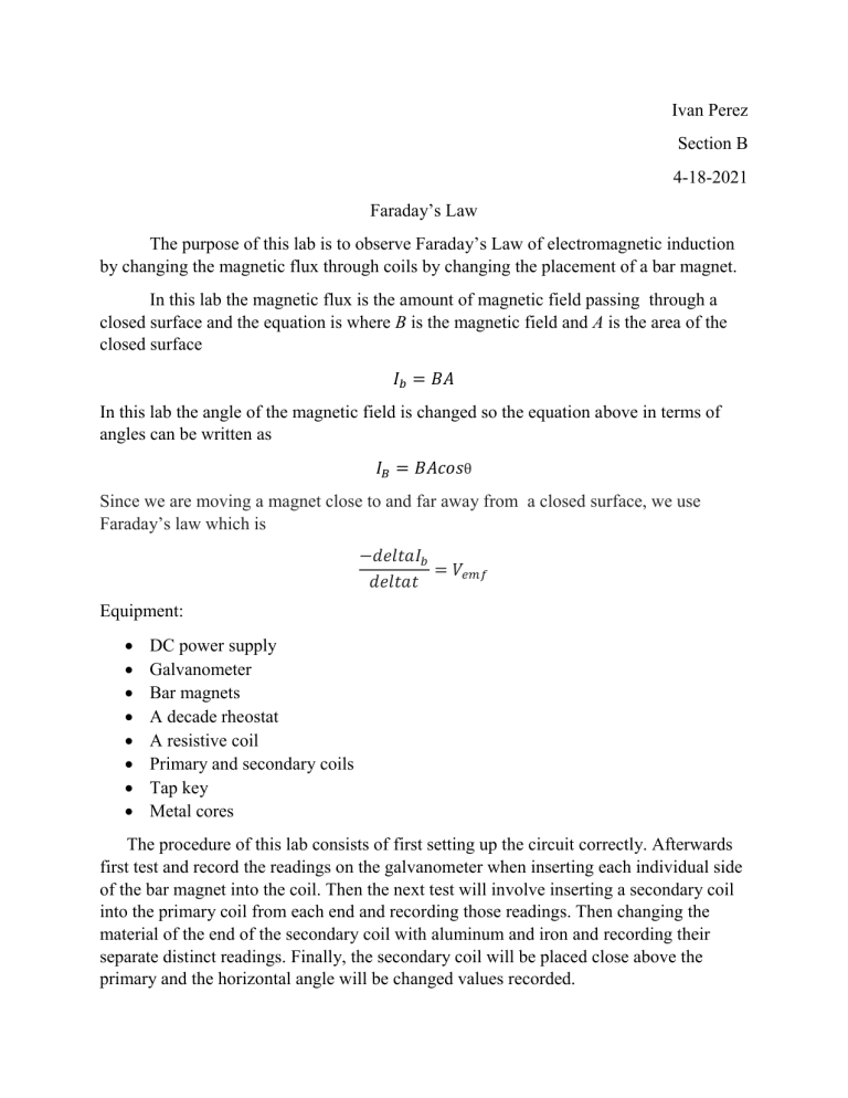
Ivan Perez Section B 4-18-2021 Faraday’s Law The purpose of this lab is to observe Faraday’s Law of electromagnetic induction by changing the magnetic flux through coils by changing the placement of a bar magnet. In this lab the magnetic flux is the amount of magnetic field passing through a closed surface and the equation is where B is the magnetic field and A is the area of the closed surface 𝐼𝑏 = 𝐵𝐴 In this lab the angle of the magnetic field is changed so the equation above in terms of angles can be written as 𝐼𝐵 = 𝐵𝐴𝑐𝑜𝑠θ Since we are moving a magnet close to and far away from a closed surface, we use Faraday’s law which is −𝑑𝑒𝑙𝑡𝑎𝐼𝑏 = 𝑉𝑒𝑚𝑓 𝑑𝑒𝑙𝑡𝑎𝑡 Equipment: DC power supply Galvanometer Bar magnets A decade rheostat A resistive coil Primary and secondary coils Tap key Metal cores The procedure of this lab consists of first setting up the circuit correctly. Afterwards first test and record the readings on the galvanometer when inserting each individual side of the bar magnet into the coil. Then the next test will involve inserting a secondary coil into the primary coil from each end and recording those readings. Then changing the material of the end of the secondary coil with aluminum and iron and recording their separate distinct readings. Finally, the secondary coil will be placed close above the primary and the horizontal angle will be changed values recorded. Data: Observation 1 When the north side of the bar was inserted the galvanometer, reading went left also when the bar was removed. When the south side of the bar was inserted, the reading went right but when it was removed the reading went left. Observation 2 When inserted from the northside the galvanometer reading went left and when inserted from the southside the reading went right. Observation 3 When the end was covered with aluminum the reading of the galvanometer was amplified, the readings form the last observation, and when the end was covered in iron the amplification was greater because iron is more susceptible than aluminum. Observation 4 When the angle of the device was altered the galvanometer reading intensity decreased as it became perpendicular to the coil then increased to the opposite reading. Angle Deflection Amount 0 45 90 135 180 150mA 75 mA 0 75 mA 150 mA Deflection Direction Right Right Left Left Secondary Current 150 39.400 0 -74.707 -89.769 Results: The galvanometer showed a positive reading when the current’s direction was inline with the direction of the circuit and read negative when it went the opposite direction. The speed at which the magnet moved determined the intensity of the reading of the galvanometer. The pole of the magnet was relevant to what was shown on the galvanometer as equal to the coil the magnet has a magnetic field. It was the iron that was ferromagnetic since it is easily magnetized because of the positioning of its magnetic moments. A source of error that may have occurred would be the readings during the experiment. As a result of the setup the galvanometer could only read impulses in order to no overload the circuit which may have caused incorrect readings. Preventing having to do impulses is a way which the experiment can be improved.


