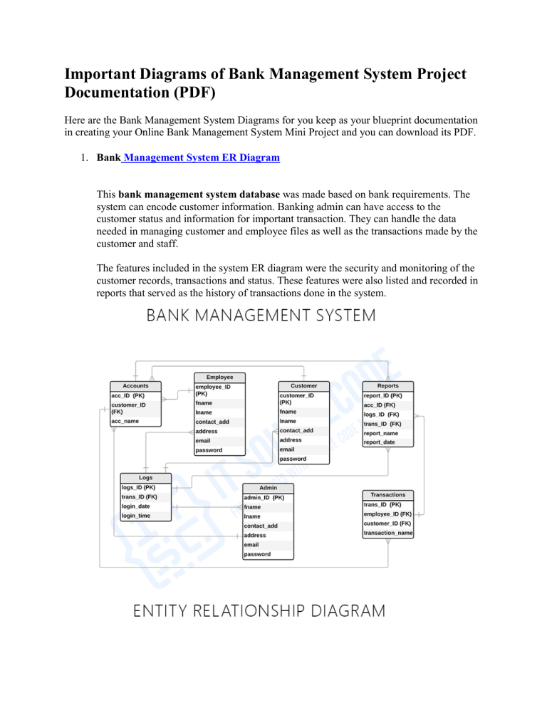
Important Diagrams of Bank Management System Project Documentation (PDF) Here are the Bank Management System Diagrams for you keep as your blueprint documentation in creating your Online Bank Management System Mini Project and you can download its PDF. 1. Bank Management System ER Diagram This bank management system database was made based on bank requirements. The system can encode customer information. Banking admin can have access to the customer status and information for important transaction. They can handle the data needed in managing customer and employee files as well as the transactions made by the customer and staff. The features included in the system ER diagram were the security and monitoring of the customer records, transactions and status. These features were also listed and recorded in reports that served as the history of transactions done in the system. 2. Bank Management System Use Case Diagram This article discusses the meaning of the Bank Management System project UML as well as its use case diagram using include and extend. A use case diagram is a visual representation of how a user might interact with a program. A use case diagram depicts the system’s numerous use cases and different sorts of users. The circles or ellipses are used to depict the use cases. 3. Bank Management System DFD Levels 0, 1 and 2 The Data Flow Diagram (DFD) represents the flow of data and the transformations in Bank Management System. In the DFD, input, processing, and output are used to represent and define the overall system. Upon reading through this article about Bank Management System you’ll then find how the system react with the user and handles data that the system is receiving from its customers. The following are the flows that the Bank Management System can generate: Manage Customers Information Manage Bank Records Checks Date of Transactions Update Customers’ Status Monitor Debit/Credit Transactions Manage Withdrawals/Savings
