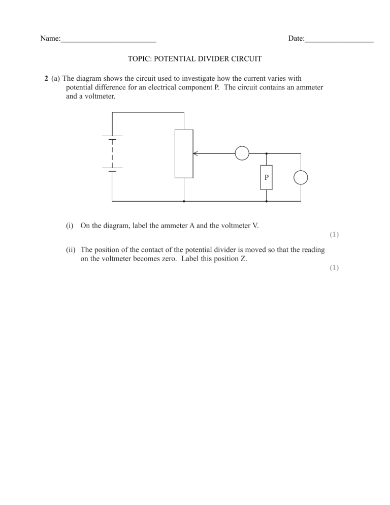
Name:_________________________ Date:__________________ TOPIC: POTENTIAL DIVIDER CIRCUIT 2 (a) The diagram shows the circuit used to investigate how the current varies with potential difference for an electrical component P. The circuit contains an ammeter and a voltmeter. P (i) On the diagram, label the ammeter A and the voltmeter V. (1) (ii) The position of the contact of the potential divider is moved so that the reading on the voltmeter becomes zero. Label this position Z. (1) (b) The graph shows how the current I varies with potential difference V for two electrical components P and Q. 0.9 0.8 0.7 0.6 Q 0.5 I/A P 0.4 0.3 0.2 0.1 0 1 2 3 4 5 6 7 8 9 10 11 12 V/V (i) State the value of the current for which the resistance of P is the same as the resistance of Q and determine this value of resistance. (3) Current = Resistance = *(ii) Component Q is a filament lamp. Explain the shape of its graph. (3) (c) A potential divider consisting of component P and a resistor R is connected to a 12 V supply. The lamp Q and a voltmeter are connected to the circuit as shown. R 12 V P Q V The supply has a negligible internal resistance. The reading on the voltmeter is 4.0 V. (i) Use the graph in part (b) to determine the current in the resistor R. (2) Current = (ii) Calculate the resistance of the resistor R. (2) Resistance = (iii) The lamp Q is removed. Explain, without further calculation, how the voltmeter reading would change. (3) (Total for Question = 15 marks) 4 A student carries out an investigation to determine how the resistance of a metal varies with temperature. A resistor is made from a coil of wire. The resistor is placed in a beaker of hot water as shown in the photograph. The resistance is measured for different temperatures of the water as it cools. (a) (i) Explain two precautions the student should take to ensure that her results are accurate. (2) (ii) The student used a thermometer and ohmmeter. State why it would have been better to use a temperature sensor and resistance sensor attached to a data logger. (1) (b) The results of the investigation are shown in the graph. 20.0 – 18.0 – 16.0 – Resistance/Ω 14.0 – 12.0 – 10.0 – 8.0 – 6.0 – 4.0 – 90 – 80 – 70 – 60 – 50 – 40 – 30 – 20 – 10 – – 0.0 – 0 – 2.0 – 100 Temperature/°C (i) The graph shows that resistance is not directly proportional to temperature in °C. State how the graph shows this. (ii) Explain the graph in terms of the structure of the metal. (1) (4) (c) The resistance of the coil of wire is 12.4 Ω at 0 °C. Calculate the length of wire in the coil. resistivity of the metal = 9.71 × 10⁻⁸ Ω m diameter of wire = 8.13 × 10⁻⁵ m (3) Length = (d) The resistor from the investigation is placed in series with a fixed resistor of resistance 24 Ω. A potential difference of 12 V is applied across the two resistors in series. Using information from the graph in (b), determine the temperature for which the potential difference across the resistor from the investigation will be 4.5 V. (3) Temperature = (Total for Question = 14 marks) 5 Photograph 1 shows a rheostat (a variable resistor). C A B Photograph 1 The rheostat is made of a long resistance wire coiled around an insulating cylinder. The turns of wire are also separated from each other by insulation of negligible thickness. The ends of the wire are connected to the sockets A and B at either end and there is a sliding contact in the centre connected to the socket C. The resistance between A and C is varied by moving the sliding contact. (a) A student decides to determine the resistivity of the material from which the wire is made by measuring the dimensions of the wire and its resistance. Photograph 2 shows a section of the rheostat and a scale. Photograph 2 (i) Take measurements from the photograph and use them to show that the crosssectional area of the wire is about 2 × 10í m2. (3) (ii) Calculate the resistivity of the material from which the wire is made. UHVLVWDQFH RI ZLUH ȍ length of wire = 12 m (3) Resistivity = (iii) Suggest an advantage for the student of using a photograph rather than taking direct measurements. (1) (b) The coil of the rheostat is 10.2 cm long. A potential difference of 12 V is applied across AB and the slider C is 7.0 cm from the end of the coil near A. Calculate the potential difference across AC. (2) Potential difference = (Total for Question = 9 marks) 6 The diagram shows a circuit set up by a student. 6V V1 ȍ V2 D %RWK YROWPHWHUV KDYH D UHVLVWDQFH RI 0ȍ 7KH UHDGLQJ RQ 91 is 6 V and the reading on V2 is zero. Explain these readings. (2) . . . . . ................................ ............................................................. . . . . . . . . . . . . . . . . . . . . . . . . . . . . .. . . . . . . . . . . . . . . . . . . . . . . . . . . . . . . . . . . . . . . . . . . . . . . . . . . . . . . . . . . . . . . . . . . . . . . . . . . . . . . . . . . . . . . . . . . . . . . . . . . . . . . . . . . . . . . . . . . . . . ................................ ............................................................. . . . . . . . . . . . . . . . . . . . . . . . . . . . . .. . . . . . . . . . . . . . . . . . . . . . . . . . . . . . . . . . . . . . . . . . . . . . . . . . . . . . . . . . . . . . . . . . . . . . . . . . . . . . . . . . . . . . . . . . . . . . . . . . . . . . . . . . . . . . . . . . . . . . ................................ ............................................................. . . . . . . . . . . . . . . . . . . . . . . . . . . . . .. . . . . . . . . . . . . . . . . . . . . . . . . . . . . . . . . . . . . . . . . . . . . . . . . . . . . . . . . . . . . . . . . . . . . . . . . . . . . . . . . . . . . . . . . . . . . . . . . . . . . . . . . . . . . . . . . . . . . . ................................ ............................................................. . . . . . . . . . . . . . . . . . . . . . . . . . . . . .. . . . . . . . . . . . . . . . . . . . . . . . . . . . . . . . . . . . . . . . . . . . . . . . . . . . . . . . . . . . . . . . . . . . . . . . . . . . . . . . . . . . . . . . . . . . . . . . . . . . . . . . . . . . . . . . . . . . . . ................................ ............................................................. . . . . . . . . . . . . . . . . . . . . . . . . . . . . .. . . . . . . . . . . . . . . . . . . . . . . . . . . . . . . . . . . . . . . . . . . . . . . . . . . . . . . . . . . . . . . . . . . . . . . . . . . . . . . . . . . . . . . . . . . . . . . . . . . . . . . . . . . . . . . . . E 7KH VWXGHQW UHSODFHV WKH ȍ UHVLVWRU ZLWK D UHVLVWRU RI XQNQRZQ UHVLVWDQFH R. The reading on V1 is now 4 V. Calculate the value of R. (3) . . . . . ................................ ............................................................. . . . . . . . . . . . . . . . . . . . . . . . . . . . . .. . . . . . . . . . . . . . . . . . . . . . . . . . . . . . . . . . . . . . . . . . . . . . . . . . . . . . . . . . . . . . . . . . . . . . . . . . . . . . . . . . . . . . . . . . . . . . . . . . . . . . . . . . . . . . . . . . . . . . ................................ ............................................................. . . . . . . . . . . . . . . . . . . . . . . . . . . . . .. . . . . . . . . . . . . . . . . . . . . . . . . . . . . . . . . . . . . . . . . . . . . . . . . . . . . . . . . . . . . . . . . . . . . . . . . . . . . . . . . . . . . . . . . . . . . . . . . . . . . . . . . . . . . . . . . . . . . . ................................ ............................................................. . . . . . . . . . . . . . . . . . . . . . . . . . . . . .. . . . . . . . . . . . . . . . . . . . . . . . . . . . . . . . . . . . . . . . . . . . . . . . . . . . . . . . . . . . . . . . . . . . . . . . . . . . . . . . . . . . . . . . . . . . . . . . . . . . . . . . . . . . . . . . . . . . . ............................................................................................. . . . . . . . . . . . . . . . . . . . . . . . . . . . . . .. . . . . . . . . . . . . . . . . . . . . . . . . . . . . . . . . . . . . . . . . . . . . . . . . . . . . . . . . . . . . . . . . . . . . . . . . . . . . . . . . . . . . . . . . . . . . . . . . . . . . . . . . . . . . . . . . R .................................................................. (Total for Question 5 marks)
